Sign In
Upload
Download
Table of Contents
Contents
Add to my manuals
Delete from my manuals
Share
URL of this page:
HTML Link:
Bookmark this page
Add
Manual will be automatically added to "My Manuals"
Print this page
×
Bookmark added
×
Added to my manuals
Manuals
Brands
Dell Manuals
Server
E14S Series
Owner's manual
Dell E14S Series Owner's Manual
Web-scale hyperconverged appliance
Hide thumbs
1
2
Table Of Contents
3
4
5
6
7
8
9
10
11
12
13
14
15
16
17
18
19
20
21
22
23
24
25
26
27
28
29
30
31
32
33
34
35
36
37
38
39
40
41
42
43
44
45
46
47
48
49
50
51
52
53
54
55
56
57
58
59
60
61
62
63
64
65
66
67
68
69
70
71
72
73
74
75
76
77
78
79
80
81
82
83
84
85
86
87
88
89
90
91
92
93
94
95
96
97
98
99
100
101
102
103
104
105
106
107
108
109
110
111
112
113
114
115
116
117
page
of
117
Go
/
117
Contents
Table of Contents
Troubleshooting
Bookmarks
Table of Contents
Table of Contents
About Your System
Supported Configurations
Front-Panel Features and Indicators
Diagnostic Indicators
Hard Drive Indicator Codes
Idrac Direct LED Indicator Codes
Back-Panel Features and Indicators
NIC Indicator Codes
Power Indicator Codes
Documentation References
Quick Resource Locator
Performing Initial System Configuration
Setting up Your System
Methods of Setting up and Configuring the Idrac IP Address
Information about Logging in to Idrac
Methods of Installing the Operating System
Remote Management
Downloading and Installing Drivers and Firmware
Pre-Operating System Management Applications
Navigation Keys
About System Setup
Entering System Setup
System Setup Main Menu
Editing System BIOS Screen Settings
Editing System Information
Editing Memory Settings
Editing Processor Settings
Editing SATA Settings
Editing Boot Settings Screen
Editing Network Settings
Editing Integrated Devices Details
Editing Serial Communication Settings
Editing System Profile
Editing System Security
Editing Miscellaneous Settings
About Boot Manager
Entering Boot Manager
Boot Manager Main Menu
Changing the Boot Order
Choosing the System Boot Mode
Assigning a System and Setup Password
Deleting or Changing an Existing System Password and Setup Password
Installing and Removing System Components
Safety Instructions
Before Working Inside Your System
After Working Inside Your System
Recommended Tools
Front Bezel (Optional)
Removing the Front Bezel
Installing the Front Bezel
Removing the System Cover
Installing the System Cover
Inside the System
Cooling Shroud
Removing the Cooling Shroud
Installing the Cooling Shroud
System Memory
General Memory Module Installation Guidelines
Mode-Specific Guidelines
Sample Memory Configurations
Removing Memory Modules
Installing Memory Modules
Hard Drives
Removing a 2.5 Inch Hard-Drive Blank
Installing a 2.5 Inch Hard-Drive Blank
Removing a Hot-Swappable Hard Drive
Installing a Hot-Swappable Hard Drive
Removing a Hard Drive from a Hard-Drive Carrier
Installing a Hard Drive into a Hard-Drive Carrier
Satadom
Important Information about SATADOM
Removing the SATADOM
Installing the SATADOM
Cooling Fans
Removing a Cooling Fan
Installing a Cooling Fan
Expansion Cards and Expansion-Card Risers
Expansion Card Installation Guidelines
Removing an Expansion Card
Installing an Expansion Card
Removing Expansion-Card Risers
Installing Expansion Card Risers
Internal Dual SD Module
Removing the Internal Dual SD Module
Installing the Internal Dual SD Module
Internal SD Card
Removing an Internal SD Card
Installing an Internal SD Card
Integrated Storage Controller Card
Removing the Integrated Storage Controller Card
Installing the Integrated Storage Controller Card
Network Daughter Card
Removing the Network Daughter Card
Installing the Network Daughter Card
Heat Sinks and Processors
Removing a Processor
Installing a Processor
Power Supply Units
Hot Spare Feature
Removing the Power Supply Unit Blank
Installing the Power Supply Unit Blank
Removing an AC Power Supply Unit
Installing an AC Power Supply Unit
Wiring Instructions for a DC Power Supply Unit
Removing a DC Power Supply Unit
Installing a DC Power Supply Unit
System Battery
Replacing the System Battery
Hard-Drive Backplane
Removing the Hard-Drive Backplane
Installing the Hard-Drive Backplane
Control Panel Assembly
Removing the Control Panel-10 Hard Drive
Installing the Control Panel-10 Hard-Drive System
System Board
Removing the System Board
Installing the System Board
Trusted Platform Module
Installing the Trusted Platform Module
Re-Enabling the TPM for Bitlocker Users
Re-Enabling the TPM for TXT Users
Troubleshooting Your System
Safety First-For You and Your System
Troubleshooting System Startup Failure
Troubleshooting External Connections
Troubleshooting the Video Subsystem
Troubleshooting a USB Device
Troubleshooting Idrac Direct (USB XML Configuration)
Troubleshooting Idrac Direct (Laptop Connection)
Troubleshooting a Serial I/O Device
Troubleshooting a NIC
Troubleshooting a Wet System
Troubleshooting a Damaged System
Troubleshooting the System Battery
Troubleshooting Power Supply Units
Power Source Problems
Power Supply Unit Problems
Troubleshooting Cooling Problems
Troubleshooting Cooling Fans
Troubleshooting System Memory
Troubleshooting an SD Card
Troubleshooting a Hard Drive
Troubleshooting a Storage Controller
Troubleshooting Expansion Cards
Troubleshooting Processors
System Messages
Warning Messages
Diagnostic Messages
Alert Messages
Using System Diagnostics
Dell Embedded System Diagnostics
When to Use the Embedded System Diagnostics
Running the Embedded System Diagnostics from Boot Manager
Running the Embedded System Diagnostics from the Dell Lifecycle Controller
System Diagnostic Controls
Jumpers and Connectors
System Board Jumper Settings
System Board Connectors
Disabling a Forgotten Password
Getting Help
Contacting Dell
Dell Supportassist
Locating Service Tag of Your System
Quick Resource Locator
Advertisement
Quick Links
1
About Your System
2
Supported Configurations
Download this manual
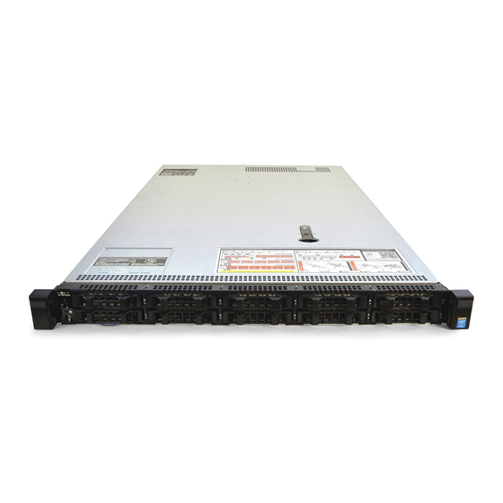
Dell XC630 Web-Scale Hyperconverged
Appliance
Owner's Manual
Regulatory Model: E14S Series
Regulatory Type: E14S001
Table of
Contents
Previous
Page
Next
Page
1
2
3
4
5
Advertisement
Table of Contents
Troubleshooting
Troubleshooting your system
98
Troubleshooting iDRAC Direct (USB XML configuration)
99
Troubleshooting iDRAC Direct (laptop connection)
100
Troubleshooting a wet system
101
Troubleshooting a damaged system
102
Troubleshooting power supply units
103
Troubleshooting cooling problems
104
Troubleshooting system memory
105
Troubleshooting an SD card
106
Troubleshooting a storage controller
107
Troubleshooting expansion cards
108
Need help?
Do you have a question about the E14S Series and is the answer not in the manual?
Ask a question
Questions and answers
Related Manuals for Dell E14S Series
Server Dell PowerEdge R515 Getting Started With Your System
(70 pages)
Server Dell PowerEdge E10S Getting Started Manual
Dell server getting started guide (51 pages)
Server Dell POWEREDGE E11S Owner's Manual
Dell server user manual (130 pages)
Server Dell Force10 C150 Configuration Manual
Ftos configuration guide ftos 8.4.2.7 e-series terascale, c-series, s-series (s50/s25) (1262 pages)
Server Dell PowerEdge R760xa Installation And Service Manual
(206 pages)
Server Dell PowerEdge R320 Owner's Manual
(143 pages)
Server Dell PowerEdge R620 Owner's Manual
Owner's manual (133 pages)
Server Dell PowerEdge XE9640 Installation And Service Manual
(272 pages)
Server Dell PowerEdge XR8000r Installation And Service Manual
(34 pages)
Server Dell E104S Installation And Service Manual
(144 pages)
Server Dell PowerEdge R770 CSP Edition Installation And Service Manual
(170 pages)
Server Dell PowerEdge R7725 Installation And Service Manual
(161 pages)
Server Dell E105S Installation And Service Manual
(114 pages)
Server Dell PowerEdge R6725 Installation And Service Manual
(130 pages)
Server Dell PowerEdge R470 Installation And Service Manual
(187 pages)
Server Dell PowerEdge R670 CSP Edition Installation And Service Manual
(155 pages)
This manual is also suitable for:
Xc630
Table of Contents
Print
Rename the bookmark
Delete bookmark?
Delete from my manuals?
Login
Sign In
OR
Sign in with Facebook
Sign in with Google
Upload manual
Upload from disk
Upload from URL


Need help?
Do you have a question about the E14S Series and is the answer not in the manual?
Questions and answers