Table of Contents
Advertisement
Quick Links
1111 W. 35th Street, Chicago, IL 60609 USA • www.tripplite.com/support
15-08-104-933289-EN.indd 1
Owner's Manual
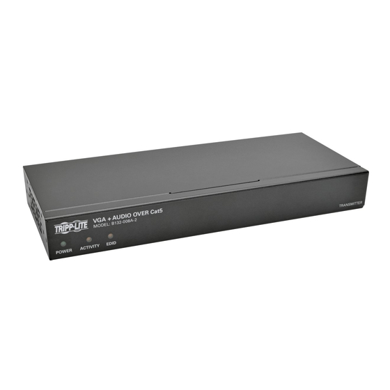
VGA Over Cat5 Extenders
and Extender/Splitters
Extender Kit Models: B130-101-2, B130-101A-2,
B130-101-WP-1, B130-101A-WP-2, B130-101S-2,
B130-111, B130-111A and B130-101-U
Transmitter Unit Models: B132-002-2,
B132-002A-2, B132-004-2, B132-004A-2 and
Receiver Unit and Remote Repeater Models:
B132-100-1, B132-100A, B132-100-WP-1,
B132-100A-WP-1, B132-110 and B132-110A
PROTECT YOUR INVESTMENT!
Register your product for quicker service
and ultimate peace of mind.
You could also win an ISOBAR6ULTRA
surge protector—a $100 value!
www.tripplite.com/warranty
Copyright © 2015 Tripp Lite. All rights reserved.
All trademarks are the sole property of their respective owners.
B132-008A-2
1
8/21/2015 3:45:46 PM
Advertisement
Table of Contents

Subscribe to Our Youtube Channel
Related Manuals for Tripp Lite B132-008A-2


Summary of Contents for Tripp Lite B132-008A-2
- Page 1 You could also win an ISOBAR6ULTRA surge protector—a $100 value! www.tripplite.com/warranty 1111 W. 35th Street, Chicago, IL 60609 USA • www.tripplite.com/support Copyright © 2015 Tripp Lite. All rights reserved. All trademarks are the sole property of their respective owners. 15-08-104-933289-EN.indd 1 8/21/2015 3:45:46 PM...
-
Page 2: Table Of Contents
Extender/Repeater Kit Installation B130-111A Non-Kit Remote Repeater B130-101-U Installation B132-002-2 Non-Kit Daisy Chain Remote B132-002A-2 Repeater Installation B132-004-2 Troubleshooting B132-004A-2 B132-008A-2 Warranty and Product Registration B132-100-1 B132-100A Additional Warnings and B132-100-WP-1 Notices B132-100A-WP-1 B132-110 B132-110A 15-08-104-933289-EN.indd 2 8/21/2015 3:45:46 PM... - Page 3 Package Contents Local Unit (L), Remote B B B B B B B B L L L L L R R R R R R Unit (R) or Both (B) 1 or 2 External Power Supplies (Input: 100-240 V, 2 2 2 2 2 2 2 0 1 1 1 1 1 1 1 1 1 1 1 50/60 Hz, 0.5 A Output: 5 V, 2 A) Mounting Hardware...
-
Page 4: Product Features
Product Features • Support a maximum resolution of 1920 x 1440 @ 60 Hz. • All operating systems supported. • Plug and play; no software or drivers required. • HDCP compliant. B130-101-2 • Extends a VGA video signal (1024 x 768 @ 60 Hz) up to 1,000 ft. from the source. -
Page 5: B130-101A
Product Features continued B130-101A-WP-2 • Extends both a VGA video (1024 x 768 @ 60 Hz) and an audio signal up to 1,000 ft. from the source. • Includes a VGA + audio splitter cable, which allows for the connection of a local monitor and speakers. -
Page 6: B130-111A
Product Features continued B130-111A • Kit comes with both local transmitter and remote repeater units. • Locate multiple monitors/speakers at different points in a chain of up to 2,000 ft. by connecting an additional remote receiver unit (B132-100A or B132-100A-WP-1), or a remote repeater unit (B132-110A). •... -
Page 7: B132-002-2
• Includes mounting hardware that allows unit to be wall-mounted, rack mounted or pole mounted. • EDID copy feature ensures optimal display compatibility. • Up to three local units can be connected to a Tripp Lite B132-004-RB rackmount bracket and mounted in just 1U of rack space. 15-08-104-933289-EN.indd 7... -
Page 8: B132-004A-2
• Includes mounting hardware that allows unit to be wall-mounted, rack mounted or pole mounted. • Up to three local units can be connected to a Tripp Lite B132-004-RB rackmount bracket and mounted in just 1U of rack space. • EDID copy feature ensures optimal display compatibility. -
Page 9: B132-100-1
• Features built-in equalization and gain controls to adjust the video image. B132-110 • Extends and expands your Tripp Lite VGA over Cat5 installation, allowing you to locate multiple monitors at different points in a chain of up to 2,000 ft. -
Page 10: B132-110A
Product Features continued B132-110A • Both extends and expands your Tripp Lite VGA + audio over Cat5 installation, allowing you to locate multiple monitors/speakers at different points in a chain of up to 2,000 ft. • Up to 4 remote units (3 remote repeaters and 1 receiver) can be connected together, providing audio/video to up to 4 remote displays/ speakers in a full chain. -
Page 11: Mounting Hardware
Note: The images below show a B140-101X DVI Extender, but mounting is the same for the VGA Extenders. The B132-004-2 and B132-004A-2 can also be mounted to a Tripp Lite B132-004-RB 1U rackmount bracket. Up to 3 B132-004-2 or B132-004A-2 local units can be connected to a B132-004-RB. -
Page 12: Installation
Installation EDID Copy Compatibility issues can occur when EDID information is not properly communicated between the source and the display. Select models include an EDID copy feature which stores a monitor’s EDID information in the transmitter and sends it to the source, ensuring optimal compatibility. - Page 13 Connect the external power supply to the transmitter unit and plug it into a Tripp Lite Surge Protector, Power Distribution Unit (PDU) or Uninterruptible Power Supply (UPS). Wait 10 seconds for the EDID information to be copied, and then disconnect the monitor from the transmitter unit’s input port and...
-
Page 14: Extender Kit Installation
Skew cable, such as Tripp Lite P524-01K. For the B130-101-U, use Zero-Skew cable for distances between 250 and 500 ft. 5. To achieve maximum resolution, it is recommended that you use Tripp Lite P502-Series VGA video or P504-Series VGA video and audio* cables with RGB coax. - Page 15 RS-232 Serial port. Connect the external power supply to the transmitter unit, and then plug it into a Tripp Lite Surge Protector, Power Distribution Unit (PDU) or Uninterruptible Power Supply (UPS). The B130-101-U gets power from the USB cable built-in to the transmitter unit and doesn’t require external power supplies.
- Page 16 DB9 cable. Connect the external power supply to the receiver unit, and then plug it into a Tripp Lite Surge Protector, Power Distribution Unit (PDU) or Uninterruptible Power Supply (UPS). The B130-101-U gets power from the USB cable built-in to the transmitter unit and doesn’t require...
-
Page 17: Non-Kit Standard Installation
For optimal image quality between 500 and 1,000 ft., use Zero- Skew cable, such as Tripp Lite P524-01K. 5. To achieve maximum resolution, it is recommended that you use Tripp Lite P502-Series VGA video or P504-Series VGA video and audio cables with RGB coax. - Page 18 Connect the external power supply to the transmitter unit, and then plug it into a Tripp Lite Surge Protector, Power Distribution Unit (PDU) or Uninterruptible Power Supply (UPS). Using Cat5e/6 cable, connect an available RJ45 OUTPUT port on the transmitter unit to the RJ45 INPUT port on a receiver unit.
-
Page 19: Non-Kit Daisy Chain Installation
For optimal image quality between 500 and 1,000 ft., use Zero- Skew cable, such as Tripp Lite P524-01K. 5. To achieve maximum resolution, it is recommended that you use Tripp Lite P502- Series VGA video or P504-Series VGA video and audio cables with RGB coax. - Page 20 Connect the external power supply to the first transmitter unit in the installation, and then plug it into a Tripp Lite Surge Protector, Power Distribution Unit (PDU) or Uninterruptible Power Supply (UPS). Repeat step 6 for each additional transmitter unit in the installation.
-
Page 21: Extender/Repeater Kit
Installation continued Extender/Repeater Kit Installation (B130-101-2, B130-101A-2, B130-111 and B130-111A) Note: 1. For models that support EDID copy, perform the EDID copy procedure described in this manual prior to installation. 2. An extender/repeater kit installation can start with a B130-101-2, B130- 101A-2, B130-111 or B130-111A. - Page 22 The use of stranded wire Cat5e/6 cable, or cable with a gauge (AWG) size higher than 24 AWG, will result in shorter extension distance. All Tripp Lite N202-Series cables are made with 24 AWG solid-wire cabling. Tripp Lite N022-01K-GY (Cat5e) and N222-01K-GY (Cat6) are 24 AWG solid-wire bulk cables.
- Page 23 Connect the external power supply to the remote repeater unit, and then plug it into a Tripp Lite Surge Protector, Power Distribution Unit (PDU) or Uninterruptible Power Supply (UPS). The Red power LED and the Green RJ45 LED will illuminate to indicate the unit is receiving power.
-
Page 24: Non-Kit Remote Repeater
2. The diagram above shows a B132-004-2 installation with the maximum number of remote units connected. B132-004A-2 and B132-008A-2 installations will be the same, except there will be audio connections and the B132-008A-2 has 8 ports. B132-002-2 and B132-002A-2 local units come with 2 ports instead of 4, and do not feature additional ports for a local monitor and speakers.*... - Page 25 The use of stranded wire Cat5e/6 cable, or cable with a gauge (AWG) size higher than 24 AWG, will result in shorter extension distance. All Tripp Lite N202-Series cables are made with 24 AWG solid-wire cabling. Tripp Lite N022-01K-GY (Cat5e) and N222-01K-GY (Cat6) are 24 AWG solid-wire bulk cables.
- Page 26 Connect the external power supply to the remote repeater unit, and then plug it into a Tripp Lite Surge Protector, Power Distribution Unit (PDU) or Uninterruptible Power Supply (UPS). The Red power LED and the Green RJ45 LED will illuminate to indicate the unit is receiving power.
-
Page 27: Non-Kit Daisy Chain Remote Repeater Installation
Installation continued Non-Kit Daisy Chain Remote Repeater Installation (B132-004-2, B132-004A-2 and B132-008A-2 only) Note: 1. For models that support EDID copy, perform the EDID copy procedure described in this manual prior to installation. 15-08-104-933289-EN.indd 27 8/21/2015 3:45:51 PM... - Page 28 2. The diagram shows a B132-004A-2 installation with the maximum number of remote units connected. A B132-008A-2 installation will be the same except for the number of ports. A B132-004-2 installation will be the same, except there will be no audio connections. B132-002-2 and B132-002A-2 local units cannot be daisy chained.
- Page 29 Connect the external power supply to the first transmitter unit in the installation, and then plug it into a Tripp Lite Surge Protector, Power Distribution Unit (PDU) or Uninterruptible Power Supply (UPS). The Red power LED and the Green RJ45 LED will illuminate to indicate the unit is receiving power.
- Page 30 VGA video and audio* cable. Connect the external power supply to the receiver unit, and then plug it into a Tripp Lite Surge Protector, Power Distribution Unit (PDU) or Uninterruptible Power Supply (UPS). Repeat steps 6 through 14 for each additional RJ45 OUTPUT port on each of the transmitter units, and then proceed to step 15.
-
Page 31: Troubleshooting
Mirror the image on both displays. 4. Compatibility issues can occur when EDID information is not properly communicated between the source and the display. Tripp Lite’s VGA over Cat5 extender kits and transmitters that have a -2 at the end of their model name include an EDID copy feature which stores a monitor’s EDID information and sends it to the source, ensuring... - Page 32 Tripp Lite’s VGA over Cat5 extender products. 8. Is your Cat5e/6 cabling wired to TIA 568B? Tripp Lite’s VGA over Cat5 extender products have been tested using Cat5e/6 cabling wired to TIA 568B (all Tripp Lite Cat5e/6 cables are wired to TIA 568B).
- Page 33 10. Do you have any patch panels or other devices in between the transmitter, repeater and receiver units? Tripp Lite’s VGA over Cat5 extender products were designed to be connected directly from the transmitter to the repeater and/or receiver via UTP cable. The more...
-
Page 34: Warranty And Product
TRIPP LITE warrants its products to be free from defects in materials and workmanship for a period of one (1) year from the date of initial purchase. TRIPP LITE’s obligation under this warranty is limited to repairing or replacing (at its sole option) any such defective products. To obtain service under this warranty, you must obtain a Returned Material Authorization (RMA) number from TRIPP LITE or an authorized TRIPP LITE service center. -
Page 35: Additional Warnings And
• Consult the dealer or an experienced radio/TV technician for help. Any changes or modifications to this equipment not expressly approved by Tripp Lite could void the user’s authority to operate this equipment. WEEE Compliance Information for Tripp Lite Customers and Recyclers (European Union) - Page 36 1111 W. 35th Street, Chicago, IL 60609 USA • www.tripplite.com/support 15-08-104 • 93-3289_revC 15-08-104-933289-EN.indd 36 8/21/2015 3:45:52 PM...
Need help?
Do you have a question about the B132-008A-2 and is the answer not in the manual?
Questions and answers