Table of Contents
Advertisement
Quick Links
Advertisement
Table of Contents

Subscribe to Our Youtube Channel
Related Manuals for HIKVISION DS-3TXX06HP-E Series


Summary of Contents for HIKVISION DS-3TXX06HP-E Series
- Page 1 100M or Gigabit Hi-PoE Switch Quick Start Guide UD17624B...
-
Page 2: Legal Information
MERCHANTABILITY, SATISFACTORY QUALITY, OR FITNESS FOR A PARTICULAR PURPOSE. THE USE OF THE PRODUCT BY YOU IS AT YOUR OWN RISK. IN NO EVENT WILL HIKVISION BE LIABLE TO YOU FOR ANY SPECIAL, CONSEQUENTIAL, INCIDENTAL, OR INDIRECT DAMAGES, INCLUDING, AMONG OTHERS, DAMAGES FOR LOSS OF... - Page 3 PUBLICITY, INTELLECTUAL PROPERTY RIGHTS, OR DATA PROTECTION AND OTHER PRIVACY RIGHTS. YOU SHALL NOT USE THIS PRODUCT FOR ANY PROHIBITED END-USES, INCLUDING THE DEVELOPMENT OR PRODUCTION OF WEAPONS OF MASS DESTRUCTION, THE DEVELOPMENT OR PRODUCTION OF CHEMICAL OR BIOLOGICAL WEAPONS, ANY ACTIVITIES IN THE CONTEXT RELATED TO ANY NUCLEAR EXPLOSIVE OR UNSAFE NUCLEAR FUEL-CYCLE, OR IN SUPPORT OF HUMAN RIGHTS ABUSES.
- Page 4 Regulatory Please take that changes or not expressly approved by the party responsible for compliance could void the user's authority to operate the equipment. FCC compliance: This equipment has been tested and found to comply with the limits for a Class A digital device, pursuant to part 15 of the FCC Rules.
- Page 5 Industry Canada ICES-003 Compliance This device meets the CAN ICES-3 (A)/NMB-3(A) standards requirements.
-
Page 6: Applicable Models
Preface Applicable Models This manual is applicable to DS-3T03XXHP series and DS-3T05XXHP series switches. Symbol Conventions The symbols that may be found in this document are defined as follows. Symbol Description Indicates a hazardous situation which, if not avoided, Danger will or could result in death or serious injury. -
Page 7: Safety Instruction
Safety Instruction Caution • During the installation and utilization of the device, please strictly conform to electrical safety rules in different nations and regions. • Use the power adapter delivered with the device only. • The device can be directly or modified to connect with IT power distribution system. -
Page 8: Product Introduction
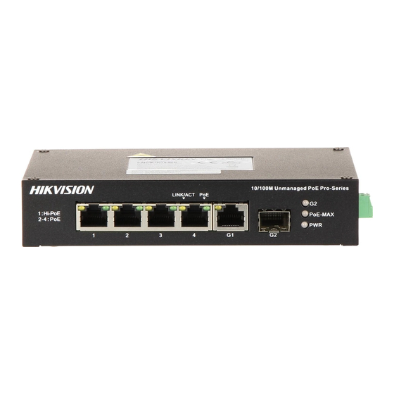
1 Introduction 1.1 Product Introduction DS-3T03XXHP series and DS-3T05XXHP series switches are layer 2 Hi-PoE switches, providing advanced PoE power supply technology and wider temperature (-30 to 65 °C, that is, -22 to 149 °F) design on the basis of high-performance access to ensure stable data upload. - Page 9 Figure 1-4 DS-3T0510HP-E Rear Panel Figure 1-5 DS-3TXX06HP-E Series Figure 1-6 DS-3TXX10HP-E Series Port/Indicator Description Indicator/Port Description • Solid /Flashing: The output power of the switch will reach the upper limit. The power supply may be abnormal if more devices are connected.
-
Page 10: Wall-Mounted Installation
Use the attached power cord to connect the switch Power Supply to socket. Support 3 modes: • Extend: Port 3 and 4 of DS-3TXX06HP-E series and port 7 and 8 of DS-3TXX10HP-E series support network transmission of up to 300 metres. DIP Switch •... -
Page 11: Connecting The Grounding Cable
2.2 Rail-Mounted Installation Steps 1. Fix the clip to the device. 2. Insert the end of DIN rail-mounted unit into the notch under the clip. Figure 2-2 Rail Mounted Installation 3. Press the DIN rail-mounted unit in quickly. 3 Grounding 3.1 Connecting the Grounding Cable Grounding is used to quickly release overvoltage and overcurrent induced by lightening for switch, and to protect personal safety. -
Page 12: Connecting Rj45 Port
2. Weld one end of the grounding cable to the angle steel or steel pipe and embalm the welding point via electroplating or coating. 3. Connect the other end of the grounding cable to the grounding terminal. Figure 3-2 Grounding with Angle Steel 3.2 Connecting RJ45 Port Use a network cable to connect the device to the RJ45 port of a peer device such as network camera, NVR, switch, etc. -
Page 13: Powering On The Device
2. Hold the SFP optical module from one side, and smoothly plug it into the device along with the SFP port slot until the optical module and the device are closely attached. 3. After powering on the device, check the status of LINK/ACT indicator.
Need help?
Do you have a question about the DS-3TXX06HP-E Series and is the answer not in the manual?
Questions and answers