
Related Manuals for Juniper NFX150


Summary of Contents for Juniper NFX150
- Page 1 NFX150 Network Services Platform Hardware Guide Modified: 2018-05-03 Copyright © 2018, Juniper Networks, Inc.
- Page 2 END USER LICENSE AGREEMENT The Juniper Networks product that is the subject of this technical documentation consists of (or is intended for use with) Juniper Networks software. Use of such software is subject to the terms and conditions of the End User License Agreement (“EULA”) posted at https://www.juniper.net/support/eula/.
-
Page 3: Table Of Contents
Power Supply in NFX150 Devices ........ - Page 4 Mounting an NFX150 Device on a Desk or Other Level Surface ... 65 Mounting an NFX150 Device on a Wall ......67 Mounting an NFX150 Device on Two Posts in a Rack .
- Page 5 Connecting the NFX150 to the Network ....... . . 77...
- Page 6 Components ............111 Returning the NFX150 Chassis or Components ......111 Contacting Customer Support to Obtain a Return Materials Authorization for an NFX150 Device .
- Page 7 Agency Approvals for NFX150 Devices ........147...
- Page 8 NFX150 Network Services Platform Hardware Guide viii Copyright © 2018, Juniper Networks, Inc.
- Page 9 Figure 19: Clearance Requirements for Airflow and Hardware Maintenance for Wall Mounting an NFX150-C-S1 Device ......46 Chapter 3 Initial Installation and Configuration .
- Page 10 Figure 35: Connecting the NFX150 Device Directly to a Management Console . . . 78 Figure 36: Installing a Transceiver in an NFX150-S1 Device ....81 Figure 37: Installing a Transceiver in an NFX150-C-S1 Device .
- Page 11 Table 3: NFX150-C (Compact Models) ........20...
- Page 12 NFX150 Network Services Platform Hardware Guide Table 32: Packing List for an NFX150 Device ......62 Table 33: NFX150 Device Mounting Methods .
-
Page 13: About The Documentation
® To obtain the most current version of all Juniper Networks technical documentation, see the product documentation page on the Juniper Networks website at https://www.juniper.net/documentation/ If the information in the latest release notes differs from the information in the documentation, follow the product Release Notes. -
Page 14: Table 1: Notice Icons
NFX150 Network Services Platform Hardware Guide Table 1: Notice Icons Icon Meaning Description Informational note Indicates important features or instructions. Caution Indicates a situation that might result in loss of data or hardware damage. Warning Alerts you to the risk of personal injury or death. -
Page 15: Documentation Feedback
We encourage you to provide feedback, comments, and suggestions so that we can improve the documentation. You can provide feedback by using either of the following methods: Online feedback rating system—On any page of the Juniper Networks TechLibrary site , simply click the stars to rate the https://www.juniper.net/documentation/index.html content, and use the pop-up form to provide us with information about your experience. -
Page 16: Requesting Technical Support
7 days a week, 365 days a year. Self-Help Online Tools and Resources For quick and easy problem resolution, Juniper Networks has designed an online self-service portal called the Customer Support Center (CSC) that provides you with the following features: Find CSC offerings: https://www.juniper.net/customers/support/... - Page 17 About the Documentation For international or direct-dial options in countries without toll-free numbers, see https://www.juniper.net/support/requesting-support.html Copyright © 2018, Juniper Networks, Inc. xvii...
- Page 18 NFX150 Network Services Platform Hardware Guide xviii Copyright © 2018, Juniper Networks, Inc.
-
Page 19: Overview
Both the models are available with or without LTE support. The NFX150 device has four 1-GbE RJ-45 ports which can be used as either access ports or as uplinks, two SFP ports, two SFP+ ports, and one management port. The NFX150 device has a 1 U form factor and comes with built-in fans and power supply. -
Page 20: System Software
15.1X53-D470 17.2R1 or later NFX150 Device Models The NFX150 device is available in five compact models and two rack mount models, with or without LTE support. All models are shipped with built-in AC power supply and have airflow-out (front-to-back) cooling. -
Page 21: Overview
Chapter 1: Overview Table 3: NFX150-C (Compact Models) (continued) NFX150-C-S1 NFX150-C-S1-AE NFX150-C-S1-AA NFX150-C-S1E-AE NFX150-C-S1E-AA 8 GB 8 GB 8 GB 16 GB 16 GB Storage 100 GB SSD 100 GB SSD 100 GB SSD 100 GB SSD 100 GB SSD... -
Page 22: Figure 1: Nfx150-C-S1
NFX150-C-S1-AA and NFX150-C-S1-AE devices. NFX150-C-S1-AA is a compact model with integrated LTE modem for Asia, Australia, and New Zealand. NFX150-C-S1-AE is a compact model with integrated LTE modem for Europe and North America. Copyright © 2018, Juniper Networks, Inc. -
Page 23: Figure 2: Nfx150-C-S1 With Integrated Lte Modem
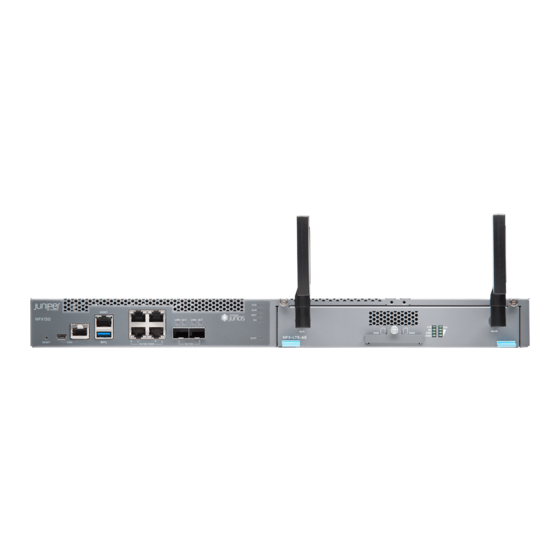
NFX150-S1, which is the rack-mount model. Figure 3: NFX150-S1 Figure 4 on page 23 shows the NFX150-S1 device with the LTE expansion module (NFX-LTE-AE and NFX-LTE-AA). Figure 4: NFX150-S1 with the LTE expansion module The LTE expansion module supports the following wireless standards:... -
Page 24: Benefits And Uses Of Nfx150
Benefits and Uses of NFX150 The NFX150 Network Services Platform provides these benefits: Highly scalable, supporting multiple Juniper and third-party VNFs on a single device. The modular software architecture provides high performance and scalability for routing, switching, and security enhanced by carrier-class reliability. -
Page 25: Chassis Physical Specifications For An Nfx150 Device
Chapter 1: Overview Chassis Physical Specifications for an NFX150 Device The NFX150 device chassis is a rigid sheet-metal structure that houses the hardware components. Table 5 on page 25 summarizes the physical specifications of the NFX150 chassis. Table 5: Physical Specifications for the NFX150 Device Chassis... -
Page 26: Rear Panel Of An Nfx150 Device
5—System status LEDs Rear Panel of an NFX150 Device Figure 9 on page 27 shows the rear panel of the NFX150-C-S1 device. The rear panel of the NFX150-C-S1 device consists of the following components: Copyright © 2018, Juniper Networks, Inc. -
Page 27: Nfx150 Interface Modules
Fans 8— Electrostatic discharge (ESD) point Figure 10 on page 27 shows the rear panel of the NFX150-S1 device. The rear panel of the NFX150-S1 device consists of the following components: Figure 10: Rear Panel Components of NFX150-S1 1— AC power cord inlet 5—... -
Page 28: Overview
Overview The LTE module operates on both 3G and 4G networks and provides wireless WAN support on the NFX150 devices. The NFX150 portfolio consists of models with or without LTE support. provides a summary of the models that support LTE. -
Page 29: Understanding The Lte Physical Interface
You can configure the dialer interface to operate in any one of the following ways: Primary interface—The dialer interface connects to the network and is always on. Backup interface for the primary WAN connection—The dialer interface is activated only when the primary connection fails. Copyright © 2018, Juniper Networks, Inc. -
Page 30: Front Panel Of An Lte Expansion Module
NFX150 Network Services Platform Hardware Guide Dial-on-demand—The dialer interface activates the connection to the wireless network only when it receives interesting traffic. The following rules apply when you configure dialer interfaces: You cannot configure the dialer interface as a constituent link in a multilink bundle. -
Page 31: Table 7: Lte Expansion Module Front Panel Components
1-4 dBi Polarization Vertical Connector type Length 120 mm The antenna is connected to the NFX150 device through the magnetic antenna base. Table 9 on page 31 lists the specifications for the antenna base. Table 9: Antenna Base Specifications Specification Value... -
Page 32: Hardware Specifications For The Lte Expansion Module
NFX150 Network Services Platform Hardware Guide Table 9: Antenna Base Specifications (continued) Specification Value Dimensions (H x W x L) 29.50 mm x 73 mm x 73 mm Hardware Specifications for the LTE Expansion Module Table 10 on page 32 provides the hardware specifications for the LTE expansion module. -
Page 33: Hardware Specifications For The Nfx-Em-6T2Sfp Expansion Module
Management Port LEDs on page 35 LTE Module LEDs on page 36 Chassis Status LEDs The front panel of an NFX150-C-S1 and NFX150-S1 devices have chassis status LEDs labeled Figure 13 on page 33 shows the chassis status LEDs in an NFX150-C-S1 device. -
Page 34: Figure 14: Chassis Status Leds In An Nfx150-S1 Device
Slot Table 12 on page 34 describes the chassis status LEDs in an NFX150 device, their colors and states, and the status they indicate. You can view the colors of the four LEDs remotely through the CLI by issuing the operational mode command... -
Page 35: Network Port And Uplink Port Leds
All four LEDs can be lit simultaneously. Network Port and Uplink Port LEDs Each network port and uplink port on the front panel of an NFX150 has two LEDs that indicate link activity and port status (see Figure 15 on page 35). -
Page 36: Lte Module Leds
NFX150 Network Services Platform Hardware Guide Table 15: Status LED on the Management Port of an NFX150 Device Color State and Description Status Green Indicates the speed. The speed indicators are: One blink per second—10 Mbps Two blinks per second—100 Mbps Three blinks per second—1000 Mbps... -
Page 37: Cooling System And Airflow In An Nfx150 Device
Chapter 1: Overview Cooling System and Airflow in an NFX150 Device The NFX150 devices have front-to-back airflow. The air intake to cool the chassis is located on the front of the chassis. Air is pulled into the chassis and pushed toward the fans, which are built-in. -
Page 38: Ac Power Supply Specifications For An Nfx150 Device
150 W Internal See Also AC Power Cord Specifications for an NFX150 Device on page 38 General Safety Guidelines and Warnings on page 117 General Electrical Safety Guidelines and Warnings on page 140 AC Power Cord Specifications for an NFX150 Device A detachable AC power cord is supplied with the AC power supplies. -
Page 39: Figure 17: Ac Plug Types
Table 18 on page Figure 17: AC Plug Types See Also General Safety Guidelines and Warnings on page 117 General Electrical Safety Guidelines and Warnings on page 140 Prevention of Electrostatic Discharge Damage on page 142 Copyright © 2018, Juniper Networks, Inc. - Page 40 NFX150 Network Services Platform Hardware Guide Copyright © 2018, Juniper Networks, Inc.
-
Page 41: Chapter 2 Site Planning, Preparation, And Specifications
Site Preparation Checklist for NFX150 Devices on page 41 NFX150 Site Guidelines and Requirements on page 43 Network Cable and Transceiver Planning for NFX150 on page 50 Transceiver and Cable Specifications, and Pinouts for NFX150 on page 54 Site Preparation Checklist for NFX150 Devices The checklist in... - Page 42 Plan the cable routing and management. Related General Safety Guidelines and Warnings on page 117 Documentation General Site Guidelines on page 43 Installing and Connecting an NFX150 Device on page 64 Mounting an NFX150 Device on page 64 Copyright © 2018, Juniper Networks, Inc.
-
Page 43: Nfx150 Site Guidelines And Requirements
Clearance Requirements for Airflow and Hardware Maintenance for an NFX150 Device on page 45 Requirements for Mounting an NFX150 Device on a Desktop or Other Level Surface on page 47 Requirements for Mounting an NFX150 Device on a Wall on page 47... -
Page 44: Environmental Requirements And Specifications For An Nfx150 Device
Seismic Complies with Zone 4 earthquake requirements as per GR-63, Issue 4 See Also Clearance Requirements for Airflow and Hardware Maintenance for an NFX150 Device on page 45 Installing and Connecting an NFX150 Device on page 64 Copyright © 2018, Juniper Networks, Inc. -
Page 45: Site Electrical Wiring Guidelines
Electrical hazards as a result of power surges conducted over the lines into the equipment Clearance Requirements for Airflow and Hardware Maintenance for an NFX150 Device When planning the site for installing an NFX150 device, you must allow sufficient clearance around the installed chassis (see... -
Page 46: Figure 18: Clearance Requirements For Airflow And Hardware Maintenance For
NFX150 Network Services Platform Hardware Guide Figure 18: Clearance Requirements for Airflow and Hardware Maintenance for an NFX150-S1 Device 24 in. (60.96 cm) 24 in. (60.96 cm) Clearance required Clearance required for maintenance for maintenance Front Rear (Ports) 19.0 in. -
Page 47: Surface
Leave at least 24 in. (61 cm) both in front of and behind the NFX150 device. For service personnel to remove and install hardware components, you must leave adequate space at the front and back of the NFX150. -
Page 48: Rack Requirements For Nfx150 Devices
45 Mounting an NFX150 Device on a Wall on page 67 Rack Requirements for NFX150 Devices You can mount the NFX150 devices on two-post racks or four-post racks. Rack requirements consist of: Rack type Mounting bracket hole spacing... -
Page 49: Cabinet Requirements For An Nfx150 Device
Mounting an NFX150 Device on Four Posts in a Rack or Cabinet Cabinet Requirements for an NFX150 Device You can mount the NFX150 device in an enclosure or cabinet that contains a four-post 19-in. open rack as defined in Cabinets, Racks, Panels, and Associated Equipment (document number EIA-310-D) published by the Electronics Industry Association. -
Page 50: Network Cable And Transceiver Planning For Nfx150
Understanding NFX150 Devices Fiber-Optic Cable Signal Loss, Attenuation, and Dispersion on page 50 Calculating the Fiber-Optic Cable Power Budget for an NFX150 Device on page 51 Calculating the Fiber-Optic Cable Power Margin for an NFX150 Device on page 52 Understanding NFX150 Devices Fiber-Optic Cable Signal Loss, Attenuation, and Dispersion To determine the power budget and power margin needed for fiber-optic connections, you need to understand how signal loss, attenuation, and dispersion affect transmission. -
Page 51: Calculating The Fiber-Optic Cable Power Budget For An Nfx150 Device
See Also Calculating the Fiber-Optic Cable Power Budget for an NFX150 Device on page 51 Calculating the Fiber-Optic Cable Power Margin for an NFX150 Device on page 52 Calculating the Fiber-Optic Cable Power Budget for an NFX150 Device Calculate the link's power budget when planning fiber-optic cable layout and distances to ensure that fiber-optic connections have sufficient power for correct operation. -
Page 52: Calculating The Fiber-Optic Cable Power Margin For An Nfx150 Device
Understanding NFX150 Devices Fiber-Optic Cable Signal Loss, Attenuation, and Dispersion on page 50 Calculating the Fiber-Optic Cable Power Margin for an NFX150 Device on page 52 Calculating the Fiber-Optic Cable Power Margin for an NFX150 Device Calculate the link's power margin when planning fiber-optic cable layout and distances... - Page 53 Refer to the specifications for your receiver to find the maximum receiver input power. See Also Understanding NFX150 Devices Fiber-Optic Cable Signal Loss, Attenuation, and Dispersion on page 50 Calculating the Fiber-Optic Cable Power Budget for an NFX150 Device on page 51 Copyright © 2018, Juniper Networks, Inc.
-
Page 54: Transceiver And Cable Specifications, And Pinouts For Nfx150
Management Port Connector Pinout Information for an NFX150 Device on page 58 Network Port Connector Pinout Information for an NFX150 Device on page 59 RJ-45 to DB-9 Serial Port Adapter Pinout Information for an NFX150 Device on page 60 Pluggable Transceivers Supported on NFX150 Devices Uplink module ports on NFX150 devices support SFP and SFP+ transceivers. -
Page 55: Cable Specifications
Standards Supported by DAC Cables on page 55 Cable Specifications NFX150 devices support SFP+ passive DAC cables. The passive Twinax cable is a straight cable with no active electronic components. NFX150 devices support 1 m, 3 m, and 5 m long SFP+ passive DAC cables. NOTE: We recommend that you use only SFP+ DAC cables purchased from Juniper Networks with your Juniper Networks device. -
Page 56: Nfx150 Devices
Cable Specifications for Console and Management Connections for the NFX150 Devices Table 26 on page 56 lists the specifications for the cables that connect the NFX150 devices to a management device. Table 26: Cable Specifications for Console and Management Connections for the NFX150 Devices Port on NFX150 Device Device... -
Page 57: Console Port Connector Pinouts For Nfx150 Devices
Table 28 on page 57 provides the pinout information for the RJ-45 console connector. An RJ-45 cable and RJ-45 to DB-9 adapter are supplied with the NFX150 device. NOTE: If your laptop or PC does not have a DB-9 male connector pin and you... -
Page 58: Usb Port Specifications For An Nfx150 Device
We strongly recommend that you use only supported USB flash drives. CAUTION: Remove the USB flash drive before upgrading Junos OS or rebooting a NFX150 device. Failure to do so could expose your device to unpredictable behavior. NOTE: Executing the... -
Page 59: Network Port Connector Pinout Information For An Nfx150 Device
LED Details of an NFX150 Device on page 33 Network Port Connector Pinout Information for an NFX150 Device A network port on an NFX150 device uses an RJ-45 connector to connect to a device. The port uses an autosensing RJ-45 connector to support a 10/100/1000Base-T connection. -
Page 60: To Db-9 Serial Port Adapter Pinout Information For An Nfx150
PC or a laptop. If your laptop or PC does not have a DB-9 male connector pin and you want to connect your laptop or PC to an NFX150 device, use a combination of the RJ-45 to DB-9 female adapter supplied with the switch along with a USB to DB-9 male adapter. -
Page 61: Device
Parts Inventory (Packing List) for an NFX150 Device on page 62 Registering Products—Mandatory for Validating SLAs on page 63 Unpacking an NFX150 Device The NFX150 devices are shipped in a cardboard carton, secured with foam packing material. The carton has an accessory compartment and contains the quick start instructions. -
Page 62: Parts Inventory (Packing List) For An Nfx150 Device
If any part on the packing list is missing, contact your customer service representative or contact Juniper customer care from within the U.S. or Canada by telephone at 1-888-314-5822. For international-dial or direct-dial options in countries without toll-free numbers, see https://www.juniper.net/support/requesting-support.html... -
Page 63: Registering Products-Mandatory For Validating Slas
Installing and Connecting an NFX150 Device on page 64 Mounting an NFX150 Device on page 64 Mounting an NFX150 Device on a Desk or Other Level Surface on page 65 Mounting an NFX150 Device on a Wall on page 67 Mounting an NFX150 Device on Two Posts in a Rack on page 71 Copyright ©... -
Page 64: Installing And Connecting An Nfx150 Device
“Mounting an NFX150 Device on Two Posts in a Rack” on page 71 (using the mounting brackets provided) Mounting an NFX150 Device on Four Posts in a Rack or Cabinet (using the separately orderable four-post rack-mount kit) “Mounting an NFX150 Device on a Wall” on page 67... -
Page 65: Mounting An Nfx150 Device On A Desk Or Other Level Surface
Mounting an NFX150 Device on a Desk or Other Level Surface You can mount an NFX150-C-S1 device on a desk or other level surface by using the four rubber feet that are shipped with the device. The rubber feet stabilize the chassis. -
Page 66: Figure 20: Attaching Rubber Feet To The Nfx150-C-S1 Device
Turn the chassis right side up on the desk or the level surface. Figure 20: Attaching Rubber Feet to the NFX150-C-S1 Device Attach the antennas to the antenna base of compact models such as NFX150-C-S1-AA and NFX150-C-S1-AE with integrated LTE modem support. See Figure 21 on page Copyright ©... -
Page 67: Mounting An Nfx150 Device On A Wall
Clearance Requirements for Airflow and Hardware Maintenance for an NFX150 Device on page 45 Mounting an NFX150 Device on a Wall You can mount an NFX150 device on a wall by using the separately orderable wall-mount kit. Before mounting an NFX150 device on a wall: Verify that the site meets the requirements described in “Site Preparation Checklist... -
Page 68: Figure 22: Attaching Wall-Mount Brackets To The Nfx150 Device Chassis
Figure 22 on page 68 Figure 23 on page Figure 22: Attaching Wall-Mount Brackets to the NFX150 Device Chassis Figure 23: Attaching Wall-Mount Brackets to the NFX150-C-S1 Device Chassis Install four mounting screws on the wall as shown in... -
Page 69: Figure 24: Measurements For Installing Mounting Screws For Nfx150-S1 Device
Chapter 3: Initial Installation and Configuration Figure 24: Measurements for Installing Mounting Screws for NFX150-S1 Device on a Wall 5.98 in (15.19 cm) 18.67 (47.42 cm) Figure 25: Measurements for Installing Mounting Screws for NFX150-C-S1 Device on a Wall 5.98 in (15.19 cm) -
Page 70: Figure 26: Mounting The Nfx150-S1 Device On A Wall
Figure 26 on page 70 Figure 27 on page Figure 26: Mounting the NFX150-S1 Device on a Wall Copyright © 2018, Juniper Networks, Inc. -
Page 71: Mounting An Nfx150 Device On Two Posts In A Rack
See Also Configuring an NFX150 Device Mounting an NFX150 Device on Two Posts in a Rack You can mount an NFX150 device on two posts of a 19-in. rack (either a two-post or a four-post rack). NOTE: If you need to mount the device in a recessed position on either a two-post rack or a four-post rack, you can use the 2-in.-recess front brackets... -
Page 72: Figure 28: Attaching The Mounting Bracket To The Side Panel Of The Device
NFX150 Network Services Platform Hardware Guide Phillips (+) screwdriver, number 2 2 mounting brackets and 8 mounting screws (provided in the accessory box shipped with the device) Screws to secure the chassis to the rack (not provided) NOTE: One person must be available to lift the device while another secures the device to the rack. -
Page 73: Connecting The Nfx150 To Power
Connecting AC Power to an NFX150 Device on page 75 Connecting Earth Ground to an NFX150 Device Earth grounding is recommended, but optional for the NFX150 device. The device functions normally without earth grounding. Electromagnetic Compatibility (EMC) and Electrostatic Discharge (ESD) requirements are met by the device chassis. The AC power cord provides surge protection. -
Page 74: Ground
This topic describes: Parts and Tools Required for Connecting an NFX150 Device to Earth Ground on page 74 Connecting Earth Ground to an NFX150 Device on page 74 Parts and Tools Required for Connecting an NFX150 Device to Earth Ground... -
Page 75: Connecting Ac Power To An Nfx150 Device
Connecting AC Power to an NFX150 Device on page 75 Connecting AC Power to an NFX150 Device The power supply in an NFX150 device is located on the rear panel. Ensure that you have the following parts and tools available:... - Page 76 The retainer brackets on your device might be above and below the power inlet rather than on either side. Figure 32: Connecting an AC Power Cord to the AC Power Cord Inlet on NFX150 Device See Also AC Power Supply Specifications for an NFX150 Device on page 38 AC Power Cord Specifications for an NFX150 Device on page 38 Copyright ©...
-
Page 77: Connecting The Nfx150 To The Network
Chapter 3: Initial Installation and Configuration Connecting the NFX150 to the Network Connecting an NFX150 Device to a Network for Out-of-Band Management on page 77 Connecting an NFX150 Device to a Management Console on page 78 Connecting an NFX150 Device to a Management Console Using Mini-USB Type-B... -
Page 78: Connecting An Nfx150 Device To A Management Console
Connecting an NFX150 Device to a Management Console on page 78 Connecting an NFX150 Device to a Management Console NFX150 device has a console port with an RJ-45 connector. Use the console port to connect the device to a management console or to a console server. -
Page 79: Connecting An Nfx150 Device To A Management Console Using Mini-Usb Type-B Console Port
If your laptop or PC does not have a DB-9 male connector pin or RJ-45 connector pin, you can connect your laptop or PC directly to an NFX150 device by using a mini-USB cable that has a Standard-A USB connector on one end and a Mini-USB Type-B (5 pin) connector on the other end. -
Page 80: Installing A Transceiver In An Nfx150 Device
(FRUs). You can remove and replace them without powering off the device or disrupting device functions. Before you begin installing a transceiver in an NFX150 device, ensure that you have taken the necessary precautions for safe handling of lasers (see “Laser and LED Safety... -
Page 81: Figure 36: Installing A Transceiver In An Nfx150-S1 Device
Do not look directly into a fiber-optic transceiver or into the ends of fiber-optic cables. Fiber-optic transceivers and fiber-optic cables connected to transceivers emit laser light that can damage your eyes. Figure 36: Installing a Transceiver in an NFX150-S1 Device Copyright © 2018, Juniper Networks, Inc. -
Page 82: Connecting A Fiber-Optic Cable To An Nfx150 Device
You can connect fiber-optic cables to the field-replaceable unit (FRU) optical transceivers installed in NFX150 devices. Before you connect a fiber-optic cable to an optical transceiver installed in an NFX150 device, ensure that you have taken the necessary precautions for safe handling of lasers (see “Laser and LED Safety Guidelines and Warnings for the NFX150 Devices”... -
Page 83: Initial Configuration On Nfx150 Devices
Figure 38: Inserting a Fiber-Optic Cable into a Transceiver on an NFX150-S1 Device Figure 39: Inserting a Fiber-Optic Cable into a Transceiver on an NFX150-C-S1 Device... -
Page 84: Enabling Basic Connectivity
Ensure that the NFX150 device is powered on. Connect to the console port: Plug one end of the Ethernet cable into the console port on your NFX150 device. Connect the other end of the Ethernet cable to the RJ-45—to—DB-9 serial port adapter shipped with your device. - Page 85 (Optional) Enable the Internet connection for devices connected on LAN by setting the DNS IP: [edit] root@# set access address-assignment pool junosDHCPPool family inet dhcp-attributes name-server dns-server-ip Commit the configuration: [edit] root@# commit Copyright © 2018, Juniper Networks, Inc.
-
Page 86: Establish The Connection
ISP. The device is assigned an IP address by the ISP through DHCP. Figure 40: Connecting the Interfaces on an NFX150-S1 Device Internet Optionally, you can obtain a SIM card from the ISP and connect the device through LTE. -
Page 87: Installing The Expansion Module
The expansion module must be installed in the first slot, which is present beside the chassis LEDs. To install the expansion module such as NFX-EM-6T2SFP in an NFX150 device: Attach an electrostatic discharge (ESD) grounding strap to your bare wrist, and connect the strap to the grounding point on the back of the device. -
Page 88: Figure 41: Attaching Antennas To The Lte Expansion Module
NFX150 Network Services Platform Hardware Guide To install the LTE expansion modules such as NFX-LTE-AE and NFX-LTE-AA in an NFX150 device: Attach an electrostatic discharge (ESD) grounding strap to your bare wrist, and connect the strap to the grounding point on the back of the device. -
Page 89: Configuring The Lte Expansion Module
Configuring the LTE Expansion Module for Primary Mode Before you begin the procedure, ensure that the logical interface (dl0.0) is not configured as a backup. If dl0.0 is configured as a backup option for any interface on the device, Copyright © 2018, Juniper Networks, Inc. - Page 90 NFX150 Network Services Platform Hardware Guide then this configuration overrides the configuration outlined in this procedure, and the LTE expansion module will function as a backup interface. Use the command to show interfaces | display set | match backup-option | match dl0.0 check whether any interface uses dl0.0 as a backup interface.
-
Page 91: Configuring The Lte Expansion Module For Dial-On-Demand Mode
0 dialer-options idle-timeout idle-timeout-value Configure the dialer pool for the LTE physical interface: user@host# set interfaces cl-1/1/0 dialer-options pool dialer-pool-number Copyright © 2018, Juniper Networks, Inc. - Page 92 NFX150 Network Services Platform Hardware Guide NOTE: is always 1 as there is only one LTE interface dialer-pool-number on the NFX150. Create the dialer filter rule: user@host# set firewall family inet dialer-filter dialer-filter-name term term1 from destination-address ip-address then note Set the default route: set routing-options static route ip-address next-hop dl0.0...
-
Page 93: Configuring The Lte Expansion Module For Backup Mode
Select the profile and configure the radio access type for the SIM card: user@host# set interfaces cl-1/1/0 cellular-options sim sim-slot-number select-profile profile-id profile-id user@host# set interfaces cl-1/1/0 cellular-options sim sim-slot-number radio-access automatic Copyright © 2018, Juniper Networks, Inc. -
Page 94: (Ota)
NFX150 Network Services Platform Hardware Guide NOTE: If a SIM card is installed in the second slot, then select the profile and configure the radio access type for the SIM card in the second slot as well. Configure the Ethernet interface as the primary interface, which connects to the wireless network. - Page 95 Integrate Circuit Card Identity (ICCID): 89860117811046631207 Reference Signal Receiving Power (RSRP): -71 Reference Signal Receiving Quality (RSRQ): -8 Signal to Interference-plus-Noise Ratio (SiNR): 19 Signal Noise Ratio (SNR): 22 Energy per Chip to Interference (ECIO): 0 Copyright © 2018, Juniper Networks, Inc.
- Page 96 NFX150 Network Services Platform Hardware Guide Related Configuring the LTE Module on NFX Devices Documentation Copyright © 2018, Juniper Networks, Inc.
-
Page 97: Maintaining Components
(FRUs). You can remove and replace them without powering off the device or disrupting device functions. Before you begin installing a transceiver in an NFX150 device, ensure that you have taken the necessary precautions for safe handling of lasers (see “Laser and LED Safety... -
Page 98: Figure 42: Installing A Transceiver In An Nfx150-S1 Device
Fiber-optic transceivers and fiber-optic cables connected to transceivers emit laser light that can damage your eyes. Figure 42: Installing a Transceiver in an NFX150-S1 Device Figure 43: Installing a Transceiver in an NFX150-C-S1 Device Copyright © 2018, Juniper Networks, Inc. -
Page 99: Removing A Transceiver From An Nfx150 Device
(FRUs). You can remove and replace them without powering off the device or disrupting device functions. Before you begin removing a transceiver from the NFX150 device, ensure that you have taken the necessary precautions for safe handling of lasers (see “Laser and LED Safety... -
Page 100: Figure 44: Removing A Transceiver From An Nfx150-S1 Device
Place the dust cover over the empty port. Figure 44: Removing a Transceiver from an NFX150-S1 Device Figure 45: Removing a Transceiver from an NFX150-C-S1 Device See Also Installing a Transceiver in an NFX150 Device on page 80 Copyright © 2018, Juniper Networks, Inc. -
Page 101: Maintaining Fiber-Optic Cables On Nfx150 Devices
Disconnecting a Fiber-Optic Cable from an NFX150 Device Before you disconnect a fiber-optic cable from an optical transceiver installed in an NFX150 device, ensure that you have taken the necessary precautions for safe handling of lasers (see “Laser and LED Safety Guidelines and Warnings for the NFX150 Devices”... -
Page 102: Connecting A Fiber-Optic Cable To An Nfx150 Device
You can connect fiber-optic cables to the field-replaceable unit (FRU) optical transceivers installed in NFX150 devices. Before you connect a fiber-optic cable to an optical transceiver installed in an NFX150 device, ensure that you have taken the necessary precautions for safe handling of lasers (see “Laser and LED Safety Guidelines and Warnings for the NFX150 Devices”... -
Page 103: Figure 46: Inserting A Fiber-Optic Cable Into A Transceiver On An Nfx150-S1
Chapter 4: Maintaining Components To connect a fiber-optic cable to an optical transceiver installed in an NFX150 device: WARNING: Do not look directly into a fiber-optic transceiver or into the ends of fiber-optic cables. Fiber-optic transceivers and fiber-optic cables connected to transceivers emit laser light that can damage your eyes. -
Page 104: Removing The Nfx150 Device From A Rack Or Cabinet
NFX150 Network Services Platform Hardware Guide Figure 47: Inserting a Fiber-Optic Cable into a Transceiver on an NFX150-C-S1 Device See Also Disconnecting a Fiber-Optic Cable from an NFX150 Device on page 101 Maintaining Fiber-Optic Cables in an NFX150 Device on page 101... - Page 105 Wrap and fasten one end of the ESD grounding strap around your wrist and connect the other end to a site ESD point. Set the power switch to OFF (O) position. Copyright © 2018, Juniper Networks, Inc.
-
Page 106: Removing An Nfx150 Device From A Rack Or Cabinet
Connecting AC Power to an NFX150 Device on page 75 Removing an NFX150 Device from a Rack or Cabinet If you need to relocate an installed NFX150 device, use the procedure described in this topic. (The remainder of this topic uses rack to mean rack or cabinet.) - Page 107 Chapter 4: Maintaining Components Chassis Lifting Guidelines for NFX150 Devices on page 123 Copyright © 2018, Juniper Networks, Inc.
- Page 108 NFX150 Network Services Platform Hardware Guide Copyright © 2018, Juniper Networks, Inc.
-
Page 109: Troubleshooting Hardware
Understanding Alarm Types and Severity Levels on NFX150 Devices on page 109 Understanding Alarm Types and Severity Levels on NFX150 Devices Alarms alert you to conditions that might prevent normal operation of the NFX150 device. Table 38 on page 109 provides a list of alarm terms and definitions that may help you in monitoring the device. - Page 110 NFX150 Network Services Platform Hardware Guide Related NFX150 Device Hardware Overview on page 19 Documentation Copyright © 2018, Juniper Networks, Inc.
-
Page 111: Components
Packing an NFX150 Device or Component for Shipping on page 114 Contacting Customer Support to Obtain a Return Materials Authorization for an NFX150 Device If you are returning a NFX150 device or component to Juniper Networks for repair or replacement, obtain a Return Materials Authorization (RMA) from the Juniper Networks Technical Assistance Center (JTAC). -
Page 112: Returning A Nfx150 Device Or Component For Repair Or Replacement
Returning a NFX150 Device or Component for Repair or Replacement on page 112 Returning a NFX150 Device or Component for Repair or Replacement If you need to return a NFX150 device or component to Juniper Networks for repair or replacement, follow this procedure: Determine the serial number of the device or component. -
Page 113: Locating The Serial Number On An Nfx150 Device
Basics and Services Command Reference at https://www.juniper.net/documentation/software/junos/index.html Locating the Chassis Serial Number ID Label on an NFX150 Device The serial number ID label is located on the back of the chassis on an NFX150 device. Figure 48 on page 114. -
Page 114: Packing An Nfx150 Device Or Component For Shipping
Device on page 111 Packing an NFX150 Device or Component for Shipping If you are returning a NFX150 device or component to Juniper Networks for repair or replacement, pack the item as described in this topic. Before you pack a NFX150 device or component: Ensure that you have taken the necessary precautions to prevent electrostatic discharge (ESD) damage. -
Page 115: Packing Nfx150 Device Components For Shipping
Close the top of the cardboard shipping box and seal it with packing tape. Write the RMA number on the exterior of the box to ensure proper tracking. See Also Returning a NFX150 Device or Component for Repair or Replacement on page 112 Copyright © 2018, Juniper Networks, Inc. - Page 116 NFX150 Network Services Platform Hardware Guide Copyright © 2018, Juniper Networks, Inc.
-
Page 117: Safety And Compliance Information
Ramp Warning on page 125 Rack-Mounting and Cabinet-Mounting Warnings on page 126 Laser and LED Safety Guidelines and Warnings for the NFX150 Devices on page 129 Radiation from Open Port Apertures Warning on page 134 Maintenance and Operational Safety Guidelines and Warnings on page 135... - Page 118 NFX150 Network Services Platform Hardware Guide Keep tools away from areas where people could trip over them while walking. Do not wear loose clothing or jewelry, such as rings, bracelets, or chains, which could become caught in the device. Wear safety glasses if you are working under any conditions that could be hazardous to your eyes.
-
Page 119: Definitions Of Safety Warning Levels
Arbeit an irgendeinem Gerät beginnen, seien Sie sich der mit elektrischen Stromkreisen verbundenen Gefahren und der Standardpraktiken zur Vermeidung von Unfällen bewußt. Avvertenza Questo simbolo di avvertenza indica un pericolo. La situazione potrebbe causare infortuni alle persone. Prima di lavorare su qualsiasi Copyright © 2018, Juniper Networks, Inc. -
Page 120: Qualified Personnel Warning
NFX150 Network Services Platform Hardware Guide apparecchiatura, occorre conoscere i pericoli relativi ai circuiti elettrici ed essere al corrente delle pratiche standard per la prevenzione di incidenti. Advarsel Dette varselsymbolet betyr fare. Du befinner deg i en situasjon som kan føre til personskade. Før du utfører arbeid på utstyr, må du vare oppmerksom på... -
Page 121: Warning Statement For Norway And Sweden
PTX5000 DC Power Electrical Safety Guidelines Warning Statement for Norway and Sweden WARNING: The equipment must be connected to an earthed mains socket-outlet. Advarsel Apparatet skal kobles til en jordet stikkontakt. Varning! Apparaten skall anslutas till jordat nätuttag. Copyright © 2018, Juniper Networks, Inc. -
Page 122: Fire Safety Requirements
To keep warranties effective, do not use a dry chemical fire extinguisher to control a fire at or near a Juniper Networks device. If a dry chemical fire extinguisher is used, the unit is no longer eligible for coverage under a service agreement. -
Page 123: Installation Instructions Warning
Laser and LED Safety Guidelines and Warnings for the ACX5000 Router Grounded Equipment Warning Chassis Lifting Guidelines for NFX150 Devices The weight of an NFX150 device is approximately 9.4 lb (4.3 kg). Observe the following guidelines for lifting and moving an NFX150 device: Copyright © 2018, Juniper Networks, Inc. -
Page 124: Restricted Access Warning
NFX150 Network Services Platform Hardware Guide Before installing the device, verify that the intended site meets the specified power, environmental, and clearance requirements. Before lifting or moving the switch, disconnect all external cables. Related General Safety Guidelines and Warnings on page 117... -
Page 125: Ramp Warning
Avvertenza Non usare una rampa con pendenza superiore a 10 gradi. Advarsel Bruk aldri en rampe som heller mer enn 10 grader. Aviso Não utilize uma rampa com uma inclinação superior a 10 graus. Copyright © 2018, Juniper Networks, Inc. -
Page 126: Rack-Mounting And Cabinet-Mounting Warnings
De onderstaande richtlijnen worden verstrekt om uw veiligheid te verzekeren: De Juniper Networks switch moet in een stellage worden geïnstalleerd die aan een bouwsel is verankerd. Dit toestel dient onderaan in het rek gemonteerd te worden als het toestel het enige in het rek is. - Page 127 Les directives ci-dessous sont destinées à assurer la protection du personnel: Le rack sur lequel est monté le Juniper Networks switch doit être fixé à la structure du bâtiment. Si cette unité constitue la seule unité montée en casier, elle doit être placée dans le bas.
- Page 128 Le seguenti direttive vengono fornite per garantire la sicurezza personale: Il Juniper Networks switch deve essere installato in un telaio, il quale deve essere fissato alla struttura dell'edificio. Questa unità deve venire montata sul fondo del supporto, se si tratta dell'unica unità...
-
Page 129: Laser And Led Safety Guidelines And Warnings For The Nfx150 Devices
Para garantizar su seguridad, proceda según las siguientes instrucciones: El Juniper Networks switch debe instalarse en un bastidor fijado a la estructura del edificio. Colocar el equipo en la parte inferior del bastidor, cuando sea la única unidad en el mismo. -
Page 130: General Laser Safety Guidelines
NFX150 Network Services Platform Hardware Guide Class 1M Laser Radiation Warning on page 130 Class 1 Laser Product Warning on page 131 Class 1 LED Product Warning on page 131 Laser Beam Warning on page 131 Unterminated Fiber-Optic Cable Warning on page 132... -
Page 131: Class 1 Laser Product Warning
Aviso Produto de classe 1 com LED. ¡Atención! Aviso sobre producto LED de Clase 1. Varning! Lysdiodprodukt av klass 1. Laser Beam Warning WARNING: Do not stare into the laser beam or view it directly with optical instruments. Copyright © 2018, Juniper Networks, Inc. -
Page 132: Unterminated Fiber-Optic Cable Warning
NFX150 Network Services Platform Hardware Guide Waarschuwing Niet in de straal staren of hem rechtstreeks bekijken met optische instrumenten. Varoitus Älä katso säteeseen äläkä tarkastele sitä suoraan optisen laitteen avulla. Attention Ne pas fixer le faisceau des yeux, ni l'observer directement à l'aide d'instruments optiques. - Page 133 (t.ex. lupper, förstoringsglas och mikroskop) från ett avstånd på 100 mm kan skada ögonen. Related General Safety Guidelines and Warnings on page 117 Documentation Radiation from Open Port Apertures Warning on page 134 Installation Instructions Warning on page 123 Grounded Equipment Warning Copyright © 2018, Juniper Networks, Inc.
-
Page 134: Radiation From Open Port Apertures Warning
NFX150 Network Services Platform Hardware Guide Radiation from Open Port Apertures Warning WARNING: Because invisible radiation might be emitted from the aperture of the port when no fiber cable is connected, avoid exposure to radiation and do not stare into open apertures. -
Page 135: Maintenance And Operational Safety Guidelines And Warnings
Kasser brukte batterier i henhold til produsentens instruksjoner. Avvertenza Pericolo di esplosione se la batteria non è installata correttamente. Sostituire solo con una di tipo uguale o equivalente, consigliata dal produttore. Eliminare le batterie usate secondo le istruzioni del produttore. Copyright © 2018, Juniper Networks, Inc. -
Page 136: Jewelry Removal Warning
NFX150 Network Services Platform Hardware Guide Aviso Existe perigo de explosão se a bateria for substituída incorrectamente. Substitua a bateria por uma bateria igual ou de um tipo equivalente recomendado pelo fabricante. Destrua as baterias usadas conforme as instruções do fabricante. -
Page 137: Lightning Activity Warning
Avvertenza Non lavorare sul sistema o collegare oppure scollegare i cavi durante un temporale con fulmini. Advarsel Utfør aldri arbeid på systemet, eller koble kabler til eller fra systemet når det tordner eller lyner. Copyright © 2018, Juniper Networks, Inc. -
Page 138: Operating Temperature Warning
6 in. (15.2 cm) of clearance around the ventilation openings. Waarschuwing Om te voorkomen dat welke switch van de Juniper Networks router dan ook oververhit raakt, dient u deze niet te bedienen op een plaats waar de maximale aanbevolen omgevingstemperatuur van 40°... -
Page 139: Product Disposal Warning
15,2 cm à volta das aberturas de ventilação. ¡Atención! Para impedir que un encaminador de la serie Juniper Networks switch se recaliente, no lo haga funcionar en un área en la que se supere la temperatura ambiente máxima recomendada de 40°... -
Page 140: General Electrical Safety Guidelines And Warnings
NFX150 Network Services Platform Hardware Guide Related General Safety Guidelines and Warnings on page 117 Documentation General Electrical Safety Guidelines and Warnings on page 140 AC Power Electrical Safety Guidelines on page 143 PTX5000 AC Power Electrical Safety Guidelines PTX5000 AC Power Electrical Safety Warnings... -
Page 141: Action To Take After An Electrical Accident
Use caution. Be aware of potentially hazardous conditions that could cause further injury. Disconnect power from the device. If possible, send another person to get medical aid. Otherwise, assess the condition of the victim, then call for help. Copyright © 2018, Juniper Networks, Inc. -
Page 142: Prevention Of Electrostatic Discharge Damage
NFX150 Network Services Platform Hardware Guide Related General Safety Guidelines and Warnings on page 117 Documentation General Electrical Safety Guidelines and Warnings on page 140 AC Power Electrical Safety Guidelines on page 143 PTX5000 AC Power Electrical Safety Guidelines PTX5000 AC Power Electrical Safety Warnings... -
Page 143: Ac Power Electrical Safety Guidelines
Equipment grounding must comply with local and national electrical codes. You must provide an external certified circuit breaker (for two-pole or four-pole based on your requirement) rated minimum 20 A in the building installation. Copyright © 2018, Juniper Networks, Inc. -
Page 144: Ac Power Disconnection Warning
NFX150 Network Services Platform Hardware Guide The power cord serves as the main disconnecting device for the AC-powered device. The socket outlet must be near the AC-powered device and be easily accessible. For devices that have more than one power supply connection, you must ensure that all power connections are fully disconnected so that power to the device is completely removed to prevent electric shock. -
Page 145: Tn Power Warning
TN. Advarsel Utstyret er utfomet til bruk med TN-strømsystemer. Aviso O dispositivo foi criado para operar com sistemas de corrente TN. ¡Atención! El equipo está diseñado para trabajar con sistemas de alimentación tipo TN. Copyright © 2018, Juniper Networks, Inc. - Page 146 NFX150 Network Services Platform Hardware Guide Varning! Enheten är konstruerad för användning tillsammans med elkraftssystem av TN-typ. Related General Safety Guidelines and Warnings on page 117 Documentation General Electrical Safety Guidelines and Warnings on page 140 Grounded Equipment Warning Multiple Power Supplies Disconnection Warning...
-
Page 147: Chapter 8 Agency Approvals And Compliance Statements
CHAPTER 8 Agency Approvals and Compliance Statements Agency Approvals for NFX150 Devices on page 147 Compliance Statements for EMC Requirements for NFX150 Devices on page 148 Agency Approvals for NFX150 Devices The NFX150 hardware devices comply with the following standards: Safety CAN/CSA-C22.2 No. -
Page 148: Compliance Statements For Emc Requirements For Nfx150 Devices
Compliance Statements for EMC Requirements for NFX150 Devices on page 148 Documentation Compliance Statements for EMC Requirements for NFX150 Devices This topic describes the EMC requirements for the NFX150 hardware devices for: Canada on page 148 European Community on page 149... -
Page 149: European Community
Japan The preceding translates as follows: This is a Class A device. In a domestic environment this device might cause radio interference, in which case the user needs to take adequate measures. VCCI-A Copyright © 2018, Juniper Networks, Inc. -
Page 150: Korea
NFX150 Network Services Platform Hardware Guide Korea Korean Class A Warning The preceding translates as follows: This equipment is Industrial (Class A) electromagnetic wave suitability equipment and seller or user should take notice of it, and this equipment is to be used in the places except... - Page 151 Chapter 8: Agency Approvals and Compliance Statements Related Agency Approvals for NFX150 Devices on page 147 Documentation Copyright © 2018, Juniper Networks, Inc.
- Page 152 NFX150 Network Services Platform Hardware Guide Copyright © 2018, Juniper Networks, Inc.
Need help?
Do you have a question about the NFX150 and is the answer not in the manual?
Questions and answers