Table of Contents
Advertisement
Quick Links
www.ti.com
User's Guide
TLV3601EVM User's Guide
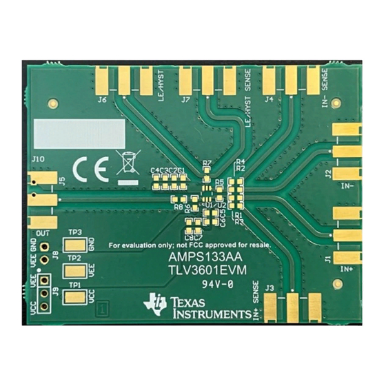
The TLV3601EVM is an evaluation board designed to evaluate the high-speed TLV3601 and TLV3603
comparators. The PCB footprint for the comparator accommodates either the 5-pin SC70 TLV3601 or the 6-pin
SC70 TLV3603 to be soldered on the board.
1
Introduction.............................................................................................................................................................................2
2
Features...................................................................................................................................................................................3
Specifications.................................................................................................................................................................4
Equipment.....................................................................................................................................................5
Procedure............................................................................................................................................................6
Setup.............................................................................................................................................................................8
6.1 Supply Voltage...................................................................................................................................................................
6.2 Inputs.................................................................................................................................................................................
6.3
Outputs...............................................................................................................................................................................9
6.4
Hysteresis...........................................................................................................................................................................9
7 Layout Guidelines.................................................................................................................................................................
8
Schematic..............................................................................................................................................................................13
9 Bill of Materials.....................................................................................................................................................................
Figure 1-1. TLV3601EVM Board Top View..................................................................................................................................
Figure 2-1. Block Diagram...........................................................................................................................................................
Figure 5-1. TLV3601 EVM Quick Start Setup..............................................................................................................................
Figure 5-2. Propagation Delay Rise Portion................................................................................................................................
Figure 6-1. TLV3601 EVM Supply Voltage Connection...............................................................................................................
Figure 6-3. Input Side Schematic................................................................................................................................................
Figure 6-4. Output Side Block Diagram.......................................................................................................................................
Figure 7-1. Layers......................................................................................................................................................................
Figure 7-2. Block Diagram.........................................................................................................................................................
Schematic........................................................................................................................................13
Trademarks
All trademarks are the property of their respective owners.
SNOU183 - MAY 2021
Submit Document Feedback
ABSTRACT
Table of Contents
List of Figures
TLV3601.........................................................................................................4
TLV3603.........................................................................................................4
Portion..................................................................................................................................7
Schematic.................................................................................................................8
Schematic...............................................................................................................................10
Schematic...............................................................................................................................10
List of Tables
..................................................................................................................................14
Copyright © 2021 Texas Instruments Incorporated
Table of Contents
8
8
11
14
2
3
6
7
8
9
9
11
12
TLV3601EVM User's Guide
1
Advertisement
Table of Contents

Related Manuals for Texas Instruments TLV3601EVM


Summary of Contents for Texas Instruments TLV3601EVM
-
Page 1: Table Of Contents
TLV3601EVM User's Guide ABSTRACT The TLV3601EVM is an evaluation board designed to evaluate the high-speed TLV3601 and TLV3603 comparators. The PCB footprint for the comparator accommodates either the 5-pin SC70 TLV3601 or the 6-pin SC70 TLV3603 to be soldered on the board. -
Page 2: Introduction
The TLV3601EVM is an evaluation board designed to evaluate the high-speed TLV3601 and TLV3603 comparators. The TLV3601EVM has layout options intended to make it simple to evaluate timing performance with different measurement tools. The output of the TLV3601 allows for direct connection to a 50 Ω terminated oscilloscope input or a high-speed, high impedance FET probe. -
Page 3: Features
5-pin (TLV3601) and 6-pin (TLV3603) SC-70 Package Feedback ¡ IN+ Sense Attenuation ¢ TLV360X – £ IN- Sense Hysteresis VCC or VEE LE/HYST LE/HYST Sense Figure 2-1. Block Diagram SNOU183 – MAY 2021 TLV3601EVM User's Guide Submit Document Feedback Copyright © 2021 Texas Instruments Incorporated... -
Page 4: Evm Specifications
Pin 4 (IN-) £ IN- Sense Pin 2 Hysteresis (VEE) VCC or VEE Pin 5 (LE/HYST) LE/HYST Sense Figure 3-2. EVM Pin Assignments for Evaluating TLV3603 TLV3601EVM User's Guide SNOU183 – MAY 2021 Submit Document Feedback Copyright © 2021 Texas Instruments Incorporated... -
Page 5: Recommended Equipment
– High bandwidth FET probe • SMA Cables/adapters – Be sure to have matched length cables for IN+SENSE, IN-SENSE, and OUT – GND Barrel SNOU183 – MAY 2021 TLV3601EVM User's Guide Submit Document Feedback Copyright © 2021 Texas Instruments Incorporated... -
Page 6: Quick Start Procedure
+2.5V High Speed Pulse Generator DC Power Supply (>500 ps Rise/Fall Time) -2.5V Figure 5-1. TLV3601 EVM Quick Start Setup TLV3601EVM User's Guide SNOU183 – MAY 2021 Submit Document Feedback Copyright © 2021 Texas Instruments Incorporated... -
Page 7: Figure 5-2. Propagation Delay Rise Portion
Figure 5-3 was measured to be 2.155 ns. Input Output Figure 5-2. Propagation Delay Rise Portion Output Input Figure 5-3. Propagation Delay Fall Portion SNOU183 – MAY 2021 TLV3601EVM User's Guide Submit Document Feedback Copyright © 2021 Texas Instruments Incorporated... -
Page 8: Board Setup
50 Ω setting is not connected. The TLV3601EVM has an optional resistor pad on the input (R5) side of the device meant for termination of the input signal. R5 can be populated with a 100 Ω resistor if applying an unterminated LVDS signal to the board. -
Page 9: Outputs
The TLV3601 needs hysteresis applied through external components R6, a feedback resistor, and R1, a series resistor for IN+. Necessary calculations for the hysteric window must be made to figure out the value of both resistors. SNOU183 – MAY 2021 TLV3601EVM User's Guide Submit Document Feedback Copyright © 2021 Texas Instruments Incorporated... -
Page 10: Tlv3601
SMA connector J6, with SMA connector J7 being the corresponding sense line for that input. – TLV3603 Hysteresis VCC or VEE (J9) LE/HYST (J6) LE/HYST Sense (J7) Figure 6-6. TLV3603 Hysteresis Schematic TLV3601EVM User's Guide SNOU183 – MAY 2021 Submit Document Feedback Copyright © 2021 Texas Instruments Incorporated... -
Page 11: Layout Guidelines
Layout Guidelines 7 Layout Guidelines Top Layer Signal Layer 1 Signal Layer 2 Bottom Layer Figure 7-1. Layers SNOU183 – MAY 2021 TLV3601EVM User's Guide Submit Document Feedback Copyright © 2021 Texas Instruments Incorporated... -
Page 12: Figure 7-2. Block Diagram
Layout Guidelines www.ti.com Feedback ¡ IN+ Sense Attenuation ¢ TLV360X – £ IN- Sense Hysteresis VCC or VEE LE/HYST LE/HYST Sense Figure 7-2. Block Diagram TLV3601EVM User's Guide SNOU183 – MAY 2021 Submit Document Feedback Copyright © 2021 Texas Instruments Incorporated... -
Page 13: Figure 8-1. Tlv3601 Evm Schematic
Schematic 8 Schematic Figure 8-1. TLV3601 EVM Schematic SNOU183 – MAY 2021 TLV3601EVM User's Guide Submit Document Feedback Copyright © 2021 Texas Instruments Incorporated... -
Page 14: Bill Of Materials
Keystone 2.5ns High-Speed Comparator with Push Pull SC70-6 TLV3603DCK Texas Instruments Output 2.5ns High-Speed Comparator with Push Pull SC70-6 TLV3601DCK Texas Instruments Output, SC70-5 TLV3601EVM User's Guide SNOU183 – MAY 2021 Submit Document Feedback Copyright © 2021 Texas Instruments Incorporated... - Page 15 STANDARD TERMS FOR EVALUATION MODULES Delivery: TI delivers TI evaluation boards, kits, or modules, including any accompanying demonstration software, components, and/or documentation which may be provided together or separately (collectively, an “EVM” or “EVMs”) to the User (“User”) in accordance with the terms set forth herein.
- Page 16 www.ti.com Regulatory Notices: 3.1 United States 3.1.1 Notice applicable to EVMs not FCC-Approved: FCC NOTICE: This kit is designed to allow product developers to evaluate electronic components, circuitry, or software associated with the kit to determine whether to incorporate such items in a finished product and software developers to write software applications for use with the end product.
- Page 17 www.ti.com Concernant les EVMs avec antennes détachables Conformément à la réglementation d'Industrie Canada, le présent émetteur radio peut fonctionner avec une antenne d'un type et d'un gain maximal (ou inférieur) approuvé pour l'émetteur par Industrie Canada. Dans le but de réduire les risques de brouillage radioélectrique à...
- Page 18 www.ti.com EVM Use Restrictions and Warnings: 4.1 EVMS ARE NOT FOR USE IN FUNCTIONAL SAFETY AND/OR SAFETY CRITICAL EVALUATIONS, INCLUDING BUT NOT LIMITED TO EVALUATIONS OF LIFE SUPPORT APPLICATIONS. 4.2 User must read and apply the user guide and other available documentation provided by TI regarding the EVM prior to handling or using the EVM, including without limitation any warning or restriction notices.
- Page 19 Notwithstanding the foregoing, any judgment may be enforced in any United States or foreign court, and TI may seek injunctive relief in any United States or foreign court. Mailing Address: Texas Instruments, Post Office Box 655303, Dallas, Texas 75265 Copyright © 2019, Texas Instruments Incorporated...
- Page 20 TI products. TI’s provision of these resources does not expand or otherwise alter TI’s applicable warranties or warranty disclaimers for TI products.IMPORTANT NOTICE Mailing Address: Texas Instruments, Post Office Box 655303, Dallas, Texas 75265 Copyright © 2021, Texas Instruments Incorporated...
Need help?
Do you have a question about the TLV3601EVM and is the answer not in the manual?
Questions and answers