Advertisement
Quick Links
TLV320AIC12KEVMB-K and TLV320AIC14KEVMB-K User's
This user's guide describes the characteristics, operation, and use of evaluation modules
TLV320AIC12KEVMB
(TLV320AIC12KEVMB-K and TLV320AIC14KEVMB-K). A complete circuit description, schematic diagram
and bill of materials are also included.
The following related documents are available through the Texas Instruments web site at www.ti.com.
1
2
3
4
5
6
7
EVM Bill of Materials
Appendix A
TLV320AIC12KEVMB/14KEVMB Schematic
Appendix B
USB-MODEVM Schematic
1
2
Default Software Screen
3
Information Tab
4
Sounds and Audio Devices Properties
5
Preset Configurations
6
Device Controls Tab
7
Control Register 1 Tab
8
Control Register 2 Tab
9
Control Register 3 Tab
10
Control Register 4 Tab
11
Control Register 5 Tab
12
Control Register 6 Tab
SMARTDM is a trademark of Texas Instruments.
2
I
C is a trademark of Koninklijke Philips Electronics N.V.
Windows is a registered trademark of Microsoft Corporation.
LabView is a trademark of National Instruments.
SLAU229B - October 2007 - Revised August 2008
Submit Documentation Feedback
and
TLV320AIC14KEVMB,
EVM-Compatible Device Data Sheets
Device
TLV320AIC12K/14K
TAS1020B
REG1117-3.3
TPS767D318
SN74LVC125A
SN74LVC1G125
SN74LVC1G07
...............................................................................................................
..............................................................................................................
..............................................................................................................
..............................................................................................................
...............................................................................................................
.................................................................................................................
.......................................................................................................
......................................................................................
..................................................................................................
.............................................................................................................
..................................................................................
......................................................................................................
.......................................................................................................
....................................................................................................
....................................................................................................
....................................................................................................
....................................................................................................
....................................................................................................
....................................................................................................
SLAU229B - October 2007 - Revised August 2008
both
as
Literature Number
SLWS115E
SLES025
SBVS001
SLVS209
SCAS290
SCES223
SCES296
Contents
.................................................................
List of Figures
..................................................................
TLV320AIC12KEVMB-K and TLV320AIC14KEVMB-K User's Guide
User's Guide
Guide
stand-alone
and
as
kits
3
3
4
6
6
7
29
32
33
8
10
12
13
14
15
16
17
17
18
18
19
1
Advertisement

Related Manuals for Texas Instruments TLV320AIC12KEVMB


Summary of Contents for Texas Instruments TLV320AIC12KEVMB
-
Page 1: Table Of Contents
(TLV320AIC12KEVMB-K and TLV320AIC14KEVMB-K). A complete circuit description, schematic diagram and bill of materials are also included. The following related documents are available through the Texas Instruments web site at www.ti.com. EVM-Compatible Device Data Sheets Device Literature Number TLV320AIC12K/14K... - Page 2 ..............USB Control Endpoint HIDSETREPORT Request ....................Data Packet Configuration ....................GPIO Pin Assignments ..............TLV320AIC12KEVMB/14KEVMB Bill of Materials ..................USB-MODEVM Bill of Materials TLV320AIC12KEVMB-K and TLV320AIC14KEVMB-K User's Guide SLAU229B – October 2007 – Revised August 2008 Submit Documentation Feedback...
-
Page 3: Evm Overview
An on-board electret microphone is also provided. Analog Interface For maximum flexibility, the TLV320AIC12KEVMB/14KEVMB is designed for easy interfacing to multiple analog sources. Samtec part numbers SSW-110-22-F-D-VS-K and TSM-110-01-T-DV-P provide a convenient 10-pin dual row header/socket combination at J1 and J2. These headers/sockets provide access to the analog input and output pins of the device. -
Page 4: Digital Interface
INP1 Digital Interface The TLV320AIC12KEVMB/14KEVMB is designed to easily interface with multiple control platforms. Samtec part numbers SSW-110-22-F-D-VS-K and TSM-110-01-T-DV-P provide a convenient 10-pin dual row header/socket combination at J4 and J5. These headers/sockets provide access to the digital control and serial data pins of the device. - Page 5 The reset and power down (RESET and PWRDN) signals are routed to J4. I C™ is actually routed from the USB-MODEVM to both connectors; however, the codec and EEPROM are only connected to J5. SLAU229B – October 2007 – Revised August 2008 TLV320AIC12KEVMB-K and TLV320AIC14KEVMB-K User's Guide Submit Documentation Feedback...
-
Page 6: Power Supplies
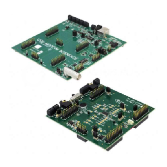
IOVDD (3.3V) J3.9 J3.10 The TLV320AIC12KEVMB-K/14KEVMB-K motherboard (the USB-MODEVM Interface board) supplies power to J3 of the TLV320AIC12KEVMB/14KEVMB. Power for the motherboard is supplied either through its USB connection or via terminal blocks on that board. Stand-Alone Operation When used as a stand-alone EVM, power can be applied to J3 directly. The user must be sure to reference the supplies to the appropriate grounds on that connector. -
Page 7: Kit Operation
The digital control signals can be applied directly to J4 and J5 (top or bottom side). The modular TLV320AIC12KEVMB/14KEVMB can also be connected directly to the USB-MODEVM Interface board included as part of the TLV320AIC12EVMB-K/14EVMB-K. See the product folder for this... - Page 8 SMARTDM Audio Interface Figure 1. TLV320AIC12KEVMB-K/14KEVMB-K Block Diagram The USB-MODEVM Interface board is intended to be used in USB mode, where control of the installed EVM is accomplished using the onboard USB controller device. Provision is made, however, for driving all the data buses (I C, PCM/SMARTDM™) externally.
- Page 9 ON: MCLK Signal is provided from USB-MODEVM J10 OFF: MCLK Signal comes from either selection of SW2-5 For use with the TLV320AIC12KEVMB/14KEVMB, SW-2 positions 1, 3, 4, 5 and 6 should be set to ON, while SW-2 positions 2, 7 and 8 should be set to OFF.
- Page 10 TAS1020B, as well as the TAS1020B digital audio interface. In the factory configuration, the board is ready to use with the TLV320AIC12KEVMB/14KEVMB. To view all the functions and configuration options available on the USB-MODEVM board, see the USB-MODEVM...
- Page 11 Below the Interface indicator is the Device Connected indicator. The TLV320AIC12K/14K Evaluation Tool detects whether or not the TLV320AIC12KEVMB-K/14KEVMB-K is present. If the device is unplugged from the USB port or if the device driver is not installed properly, the Device Connected indicator will turn red.
- Page 12 TLV320AIC12K/14K. In this configuration, the TLV320AIC12K/14K can transmit and receive audio data to/from an external PCM device or DSP. SW2 on the USB-MODEVM must be configured as shown in the right section of Figure TLV320AIC12KEVMB-K and TLV320AIC14KEVMB-K User's Guide SLAU229B – October 2007 – Revised August 2008 Submit Documentation Feedback...
- Page 13 Load button. At the same time, this will show the preset's executed commands on the Command Buffer of the Command Line Interface tab (see Figure 13). SLAU229B – October 2007 – Revised August 2008 TLV320AIC12KEVMB-K and TLV320AIC14KEVMB-K User's Guide Submit Documentation Feedback...
- Page 14 The Device Position control lets the user select a specific codec on a master-slave chain to write to or read from. The TLV320AIC12KEVMB-K/14KEVMB-K is configured as a stand-alone slave, so the device position must be set to zero. The Program Device button, when pushed, programs the register corresponding only to the selected Control Registers sub tab.
- Page 15 The indicator below each switch will light when on only if the register data sent by pressing the Program Device button is acknowledged. SLAU229B – October 2007 – Revised August 2008 TLV320AIC12KEVMB-K and TLV320AIC14KEVMB-K User's Guide Submit Documentation Feedback...
- Page 16 C address. The last 4 bits of the address will depend on the automatic cascade detection (ACD) feature of SMARTDM™, which sets the device position. TLV320AIC12KEVMB-K and TLV320AIC14KEVMB-K User's Guide SLAU229B – October 2007 – Revised August 2008 Submit Documentation Feedback...
- Page 17 FS=MCLK÷(16×P×M×N). The PLL Method switch illustrates that for coarse sampling, P must be equal to 8. Please note that the FS calculator and the PLL Method SLAU229B – October 2007 – Revised August 2008 TLV320AIC12KEVMB-K and TLV320AIC14KEVMB-K User's Guide Submit Documentation Feedback...
- Page 18 Note that OUTP2/P3 are only available on the TLV320AIC12/12K. The TLV320AIC12KEVMB/14KEVMB provides a 1/8" audio jack (J8) to connect a microphone, an on-board electret microphone (MK1) and another 1/8" audio jack (J11) to connect a stereo headset. There are four options for the Analog Input Select control: a.
- Page 19 If set to single-ended, OUTMV becomes a virtual ground for OUTP2/P3 at the common mode voltage of 1.35V. Switch SW2 on the TLV320AIC12KEVMB/14KEVMB can be used to try multiple output configurations on J7 and J11. Please see the Functional Description section on the TLV320AIC12K/14K datasheet for details.
- Page 20 The final menu item is Exit, which terminates the TLV320AIC12K/14K Evaluation Tool software. TLV320AIC12KEVMB-K and TLV320AIC14KEVMB-K User's Guide SLAU229B – October 2007 – Revised August 2008 Submit Documentation Feedback...
- Page 21 Figure 15. Options Menu Under the Help menu is an About... menu item (Figure 16) which displays information about the TLV320AIC12KEVMB/14KEVMB software. SLAU229B – October 2007 – Revised August 2008 TLV320AIC12KEVMB-K and TLV320AIC14KEVMB-K User's Guide Submit Documentation Feedback...
- Page 22 0x09 SET_REPORT wValue 0x00 don't care wIndex 0x03 HID interface is index 3 wLength calculated by host Data Data packet as described below TLV320AIC12KEVMB-K and TLV320AIC14KEVMB-K User's Guide SLAU229B – October 2007 – Revised August 2008 Submit Documentation Feedback...
- Page 23 C interfaces, the reg address as sent for SPI interfaces, the read back data from SPI line for transmission of the corresponding byte [4..60] echo of data packet sent SLAU229B – October 2007 – Revised August 2008 TLV320AIC12KEVMB-K and TLV320AIC14KEVMB-K User's Guide Submit Documentation Feedback...
- Page 24 The return packet should be 0x21 0x80 0x02 0x01 0x45 0xA0 assuming that the values we wrote above starting at Register 5 were actually written to the device. TLV320AIC12KEVMB-K and TLV320AIC14KEVMB-K User's Guide SLAU229B – October 2007 – Revised August 2008 Submit Documentation Feedback...
- Page 25 0x00 --> this value is ignored 0x01 --> length - ALWAYS a 1 0x00 --> this value is ignored The return packet should be: 0x28 0x00 0x01 0x00 0x3F SLAU229B – October 2007 – Revised August 2008 TLV320AIC12KEVMB-K and TLV320AIC14KEVMB-K User's Guide Submit Documentation Feedback...
- Page 26 SPI mode). Following these two bytes are data, if writing; if reading, the third byte value is the number of bytes to read, (expressed in hexadecimal). TLV320AIC12KEVMB-K and TLV320AIC14KEVMB-K User's Guide SLAU229B – October 2007 – Revised August 2008 Submit Documentation Feedback...
- Page 27 The previous command writes registers 1, 2, 3, 4A, 5C and 6. It will not increment from 3 to 4A and then to 4B. The subregister to be written will depend on the data. SLAU229B – October 2007 – Revised August 2008 TLV320AIC12KEVMB-K and TLV320AIC14KEVMB-K User's Guide Submit Documentation Feedback...
- Page 28 # reg 06 - MICIN with external common mode, OUTP2/P3 drivers on. w 80 06 1C # reg 01 - Continuous data transfer mode, 16 bits. w 80 01 41 TLV320AIC12KEVMB-K and TLV320AIC14KEVMB-K User's Guide SLAU229B – October 2007 – Revised August 2008 Submit Documentation Feedback...
- Page 29 EVM Bill of Materials www.ti.com EVM Bill of Materials Table 10 Table 11 contain a complete bill of materials for the modular TLV320AIC12KEVMB/14KEVMB and the USB-MODEVM Interface Board. Table 10. TLV320AIC12KEVMB/14KEVMB Bill of Materials REFERENCE DESIGNATOR DESCRIPTION MANUFACTURER MFG PART NUMBER R7, R8 0Ω...
- Page 30 Single IC buffer driver with Texas Instruments SN74LVC1G07DBVR open drain o/p Single 3-state buffer Texas Instruments SN74LVC1G125DBVR 64K 2-Wire serial EEPROM Microchip 24LC64I/SN USB-MODEVM PCB Texas Instruments 6463995 TLV320AIC12KEVMB-K and TLV320AIC14KEVMB-K User's Guide SLAU229B – October 2007 – Revised August 2008 Submit Documentation Feedback...
- Page 31 Samtec TSW-103-07-L-D 0.1" spacing SMT, half-pitch C&K Division, ITT TDA02H0SK1 2-position switch SMT, half-pitch C&K Division, ITT TDA08H0SK1 8-position switch Jumper plug Samtec SNT-100-BK-T SLAU229B – October 2007 – Revised August 2008 TLV320AIC12KEVMB-K and TLV320AIC14KEVMB-K User's Guide Submit Documentation Feedback...
- Page 32 Appendix A www.ti.com Appendix A TLV320AIC12KEVMB/14KEVMB Schematic The schematic diagram is provided as a reference. TLV320AIC12KEVMB/14KEVMB Schematic SLAU229B – October 2007 – Revised August 2008 Submit Documentation Feedback...
- Page 33 REVISION HISTORY ENGINEERING CHANGE NUMBER APPROVED /J1B /J4B OUTM1 A0(-) A0(+) OUTP1 CNTL GPIO0 A1(-) A1(+) OUTP2 CLKX DGND OUTMV A2(-) A2(+) OUTMV CLKR GPIO1 A3(-) A3(+) OUTP3 GPIO2 AGND DGND AGND GPIO3 AGND GPIO4 RESET VCOM AGND REF- TOUT DGND AGND REF+...
- Page 34 REVISION HISTORY ENGINEERING CHANGE NUMBER APPROVED OUTP1 OUTP1 IOVDD OUTP1 OUTM1 TP17 0.1uF OUTM1 PWDN PWDN PWDN OUTM1 IOVDD OUT1 OUTP2 +3.3VA OUTMV TP28 DRVSS OUTP3 TP11 AGND 10uF OUT2 TP18 TP12 DGND TP19 0.1uF DOUT DOUT DOUT OUTP2 C22 47uF OUTP2 OUTP2 TP20...
- Page 35 Appendix B www.ti.com Appendix B USB-MODEVM Schematic The schematic diagram is provided as a reference. SLAU229B – October 2007 – Revised August 2008 USB-MODEVM Schematic Submit Documentation Feedback...
- Page 36 REVISION HISTORY ENGINEERING CHANGE NUMBER APPROVED USB Interface Daughtercard Interface USB Interface Daughtercard Interface MCLK MCLK BCLK BCLK LRCLK LRCLK I2SDIN I2SDIN I2SDOUT I2SDOUT MISO MISO MOSI MOSI SCLK SCLK RESET RESET PWR_DWN PWR_DWN P3.3 P3.3 P3.4 P3.4 P3.5 P3.5 P1.0 P1.0 P1.1...
- Page 37 REVISION HISTORY ENGINEERING CHANGE NUMBER APPROVED IOVDD C32 +3.3VD +3.3VD 0.1uF 0.1uF 0.1uF +3.3VD IOVDD +3.3VD C34 IOVDD +3.3VD IOVDD +3.3VD +3.3VD SN74LVC1G126DBV VCCA VCCB USB MCK DIR1 0.1uF 0.1uF 0.1uF EXT MCK EXT MCLK DIR2 0.1uF 200k 2.7K 2.7K VCCB VCCA USB I2S...
- Page 38 REVISION HISTORY ENGINEERING CHANGE NUMBER APPROVED JMP5 A0(-) A0(+) CNTL GPIO0 A1(-) A1(+) CLKX DGND A2(-) A2(+) CLKR GPIO1 A3(-) A3(+) GPIO2 AGND DGND AGND GPIO3 AGND GPIO4 IOVDD VCOM AGND REF- TOUT DGND +3.3VD AGND REF+ GPIO5 J13A (TOP) = SAM_TSM-105-01-L-DV-P +5VA DAUGHTER-ANALOG J13B (BOTTOM) = SAM_SSW-105-22-F-D-VS-...
- Page 39 EVALUATION BOARD/KIT IMPORTANT NOTICE Texas Instruments (TI) provides the enclosed product(s) under the following conditions: This evaluation board/kit is intended for use for ENGINEERING DEVELOPMENT, DEMONSTRATION, OR EVALUATION PURPOSES ONLY and is not considered by TI to be a finished end-product fit for general consumer use. Persons handling the product(s) must have electronics training and observe good engineering practice standards.
- Page 40 IMPORTANT NOTICE Texas Instruments Incorporated and its subsidiaries (TI) reserve the right to make corrections, modifications, enhancements, improvements, and other changes to its products and services at any time and to discontinue any product or service without notice. Customers should obtain the latest relevant information before placing orders and should verify that such information is current and complete.
Need help?
Do you have a question about the TLV320AIC12KEVMB and is the answer not in the manual?
Questions and answers