Table of Contents
Advertisement
Quick Links
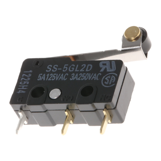
Subminiature Basic Switch
Subminiature Basic Switch Offers Long
Life of 30,000,000 Operations
A design that combines simplicity and stability by
the use of two split springs ensures a long service
life of 30,000,000 operations.
A variety of models are available, with operating
force ranging from low to high.
Solder, quick-connect terminals (#110) and PCB
terminals are available.
Approval obtained for standards including UL,
CSA, and VDE.
Ordering Information
Model Number Legend
SS-jjjjj
1
2
3
4
5
1.
Ratings
10: 10.1 A at 125 VAC
5:
5 A at 125 VAC
01: 0.1 A at 30 VDC
2.
Actuator
None: Pin plunger
GL:
Hinge lever
GL13: Simulated roller lever
GL2: Hinge roller lever
3.
Maximum Operating Force (see note 1)
None: 1.47 N {150 gf}
-F:
0.49 N {50 gf} (0.1 A, 5 A)
-E:
0.25 N {25 gf} (0.1 A)
Contact Form
SPDT
SPST-NC
168
4.
Contact Form
None: SPDT
-2:
-3:
5.
Terminals
None: Solder terminals
T:
D:
Note: 1. These values are for the pin plunger models.
2. The PCB terminals has a right-angle terminal option.
3. When suffix "-T" is placed after the model number, the
SPST-NO
SPST-NC
SPST-NO
Quick-connect terminals (#110)
PCB terminals (see note 2)
D1: Left-angled terminals
D2: Right-angled terminals
model withstands high temperatures (–25°C to 120°C).
SS
RCEW
Advertisement
Table of Contents

Subscribe to Our Youtube Channel
Related Manuals for Omron SS Series


Summary of Contents for Omron SS Series
- Page 1 Subminiature Basic Switch Subminiature Basic Switch Offers Long Life of 30,000,000 Operations A design that combines simplicity and stability by the use of two split springs ensures a long service life of 30,000,000 operations. A variety of models are available, with operating force ranging from low to high.
-
Page 2: List Of Models
0.49 N {50 gf} SS-10GL SS-10GLT SS-10GLD Simulated roller lever 0.49 N {50 gf} SS-10GL13 SS-10GL13T SS-10GL13D Hinge roller lever 0.49 N {50 gf} SS-10GL2 SS-10GL2T SS-10GL2D Note: Consult your OMRON sales representative for details on SPST-NO and SPST-NC models. -
Page 3: Specifications
Specifications Ratings Item Resistive load Model Rated voltage SS-10 250 VAC 10.1 A SS-5 125 VAC 250 VAC SS-01 125 VAC 0.1 A 30 VDC 0.1 A Note: The ratings values apply under the following test conditions: Ambient temperature: 20±2°C Ambient humidity: 65±5% Operating frequency: 30 operations/min Switching Capacity per Load (Reference Values) - Page 4 3. For the pin plunger models, the above values apply for use at both the free position and total travel position. For the lever models, they apply at the total travel position. 4. Lever-type models: Total travel position (with a contact separation time of 1 ms max.) 5. For testing conditions, contact your OMRON sales representative. Approved Standards Contact Specifications...
-
Page 5: Mounting Holes
Engineering Data (Reference Values) Mechanical Durability (Pin Plunger Models) Electrical Durability (Pin Plunger Models) SS-5, SS-1, SS-01 Models SS-5 Models 5,000 Ambient temperature: 20±2°C Ambient temperature: 20±2°C Ambient humidity: 65±5% Ambient humidity: 65±5% Operating frequency: 30 operations/min Without load 3,000 40,000 cosφ... - Page 6 2. Besides the SS-jGL models with a hinge lever length of 14.5, the SS-jGL11 models with a hinge lever length of 18.5, the SS-jGL111 models with a hinge lever length of 22.6, and the SS-jGL1111 models with a hinge lever length of 37.8 are available. Contact your OMRON representative for these models Model...
- Page 7 Simulated Roller Lever Models 15.8 1.3R t = 0.3 SS-01GL13(-E, -F) (see note) SS-5GL13(-F) SS-10GL13 +0.075 2.35 –0.05 10.2 +0.075 2.5±0.07 dia. 2.35 Three, 1.6 dia. dia. holes –0.05 Note: Stainless-steel spring lever 9.5±0.1 19.8 Model SS-01GL13-E SS-01GL13-F SS-01GL13 SS-10GL13 SS-5GL13-F SS-5GL13 OF max.
- Page 8 Precautions Using Micro Loads Refer to pages 26 to 31 for common precautions. Cautions Using a model for ordinary loads to open or close the contact of a micro load circuit may result in faulty contact. Use models that oper- Terminal Connection ate in the following range.
-
Page 9: Correct Use
General Information General Information Correct Use Electrical Conditions Area Item Page Load Using Switches The switching capacity of a switch significantly differs depending on Selecting Correct Switch whether the switch is used to break an alternating current or a direct Electrical Load current. -
Page 10: General Information
General Information General Information Contact Protective Circuit Apply a contact protective circuit (surge killer) to extend contact du- When a switch is used under high humidity, arcs resulting from cer- rability, prevent noise, and suppress the generation of carbide or ni- tain types of load (e.g., inductive loads) will generate nitrious oxides tric acid due to arc. -
Page 11: Mechanical Conditions
General Information General Information Mechanical Conditions Switching Speed and Frequency The switching frequency and speed of a switch have a great influ- Operating Stroke Setting ence on the performance of the switch. Pay attention to the follow- The setting of stroke is very important for a switch to operate with ing. - Page 12 General Information General Information • Incorrect Do not modify the actuator. If the actuator is modified, excessive external force may be applied to the internal switch mechanism, Snap-back characteristics may change, and the switch may stop Shock operation functioning. • If an external actuator is used as an operating object, check the material and thickness of the lever to make sure that the force applied to the lever is within the permissible range.
- Page 13 General Information General Information terminals, otherwise the terminal may be deformed or the housing Operation and Storage Environment may be damaged. Handling Wiring Work Do not apply oil, grease, or other lubricants to the sliding parts of a When wiring a switch, check the insulation distance between the switch.
- Page 14 General Information General Information Switch Trouble and Corrective Action Type Location Failure Possible cause Corrective action of failure Failures Contact Contact Dust and dirt on the contacts. Remove the cause of the problem, place related to l t d t f il failure the switch in a box, or use a sealed...
-
Page 15: Ordering Information
2. Unless otherwise specified, a tolerance of ±0.4 mm applies to all dimensions. 3. For operating characteristics of models not listed above, consult your OMRON sales representative. 4. The operating characteristics are for operation in the A direction ( ). - Page 16 Connectors Connectors Connectors Microswitches for tab-terminals listed in this catalog are compatible with other companies‘ products. The following AMP-made Connectors are also available. For more details about AMP Connectors, contact one of the addresses listed below. Tyco Electronics/AMP Japan Great Britain •...
Need help?
Do you have a question about the SS Series and is the answer not in the manual?
Questions and answers