Advertisement
Quick Links
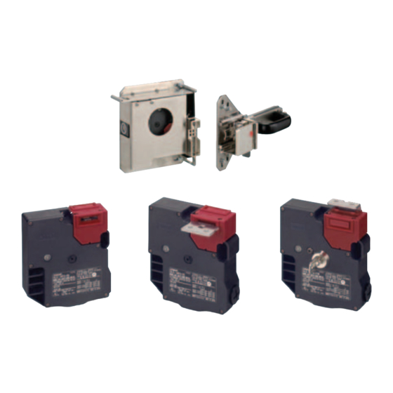
Guard Lock Safety-door Switch/Slide key
D4JL/D4JL-SK40
Holding Force of 3,000 N
• Two safety circuits and two monitor contacts provide an
array of monitoring patterns.
• Standard gold-clad contacts enable use with ordinary loads
and microloads.
• Models with trapped keys prevent workers from being locked
in hazardous work areas.
• Models with rear release buttons allow people to unlock the
Switch and escape if they are locked into hazardous areas.
• IP67 degree of protection
Be sure to read the "Safety Precautions" on page 24.
Features
Plastic Guard Lock Safety-door Switches
Rank Among the Strongest in the World
A holding force of 3,000 N makes these Switches suitable for large,
heavy doors.
Two Safety Circuits and Two Monitor
Contacts
The D4JL has two safety circuits. It also has two contacts to
separately monitor the open/closed status of the door and the status
of the lock.
Door Open/Closed
Lock Monitor Switch
Detection Switch
41
42
11
51
52
21
63
64
33
Monitoring
Monitoring the open/
the door lock
closed status of the door
12
To safety circuit
To safety circuit
22
To control circuit
34
Slide keys
Guard Lock Safety-door Switch
For the most recent information on models that have been certified for
safety standards, refer to your OMRON website.
Wide variations to protect workers who
enter hazardous areas.
• Models with Trapped Keys (mechanical lock models only)
As long as a person has the trapped key when he enters a
hazardous area, he does not have to worry about somebody
locking the door and trapping him inside.
The door can be opened only by supplying power to the solenoid
and then turning the trapped key to unlock the D4JL.
There are thirty different types of trapped keys available for use in
applications with adjacent hazardous areas.
• Models with Rear Release Buttons
A rear release button allows the door to be unlocked from inside a
hazardous area in an emergency.
Rear release button
D4JL-@@@A-06
• Special Slide Key
A special Slide Key shortens the lead time for mounting design.
The padlock that can be attached to the disable-prevention cover
prevents other workers from restarting machines.
(See page 5 for details.)
CSM_D4JL_D4JL-SK40_DS_E_7_2
Rear release button
D4JL-@@@A-@8-01-SJ
1
Advertisement

Related Manuals for Omron D4JL-SK40


Summary of Contents for Omron D4JL-SK40
- Page 1 Be sure to read the “Safety Precautions” on page 24. Guard Lock Safety-door Switch For the most recent information on models that have been certified for safety standards, refer to your OMRON website. Features Plastic Guard Lock Safety-door Switches Wide variations to protect workers who Rank Among the Strongest in the World enter hazardous areas.
- Page 2 D: 24 VDC (orange LED indicator) 6. Release Key Type 5: Standard release key 7. Connection Method N: Connector type 8. Cover Mounting Screws T: Standard screws X: Special screws Note: For more information about connector types, contact your OMRON sales representative.
- Page 3 D4JL/D4JL-SK40 Ordering Information Switches (Operation Keys are sold separately.) Consult with your OMRON representative when ordering any models that are not listed in this table. Standard Models : Models with certified direct opening contacts. Contact configuration Release key type Indicator...
- Page 4 D4JL/D4JL-SK40 Models with Trapped Keys : Models with certified direct opening contacts. Contact configuration Release key type Indicator Lock and release types (door open/closed detection switch and Conduit opening Model lock monitor switch contacts) G1/2 D4JL-2NFA-C7-01 2NC/1NO+2NC/1NO D4JL-4NFA-C7-01 G1/2 D4JL-2PFA-C7-01...
- Page 5 Note: 1. The Door Switch is not included. Select the Door Switch depending on the necessary number of contacts and the conduit size. 2. Perform risk assessment for the equipment in question, configure relay units and other safety circuits, and use properly. 3. Ask your OMRON representative for information on the D4JL-SK30. D4JL-SK40...
- Page 6 D4JL/D4JL-SK40 Specifications Standards and EC Directives Solenoid Coil Characteristics Conforms to the following EC Directives: Item Type 24 VDC • Machinery Directive Rated operating voltage +10% 24 VDC • Low Voltage Directive −15% (100% ED) • EN 1088 Current consumption Approx.
- Page 7 Switch damage or malfunctioning may occur. *2. The durability is for an ambient temperature of 5 to 35°C and an ambient humidity of 40% to 70%. For further conditions, consult your OMRON sales representative.
- Page 8 D4JL/D4JL-SK40 Connections Internal Circuit Diagram Circuit Connection Example Indicator (Examples for the D4JL-@NF@-@) • Terminals 11-42 and terminals 21-52 are connected internally and 24 VDC so connect terminals 12-41 and 22-51 for safety-circuit input O1 (+) (GS-ET-19). O2 (−) Solenoid (−)
- Page 9 D4JL/D4JL-SK40 Operation Method Operation Principles Mechanical Lock Models Solenoid Lock Models Operation Key removed. Operation Key removed. Cross-sectional view B-B Cross-sectional view B-B Operation Key inserted: Door locked. Operation Key inserted: Door unlocked. Cross-sectional view B-B Cross-sectional view B-B Solenoid ON: Door unlocked.
- Page 10 D4JL/D4JL-SK40 Trapped Key Models (1) Operation Key removed, solenoid OFF, and trapped key Operation Key inserted, solenoid ON, and trapped key inserted. removed. Status: Door locked and trapped key can be removed. Cross-sectional view B-B Cross-sectional view B-B (2) Operation Key inserted, solenoid OFF, and trapped key (5) Operation Key inserted, solenoid ON, and trapped key removed.
- Page 11 D4JL/D4JL-SK40 Structure and Nomenclature Structure (D4JL-@@@A-@5 and D4JL-@@@G-@5) Operation Key hole Solenoid Operation Key hole Example for Terminal E1 (+) D4JL-@N@@-@5 Terminal E2 (−) Lock Monitor Door Open/Closed Terminal 01 Switch Detection Switch Terminal 02 Terminal 11 To safety circuit...
- Page 12 D4JL/D4JL-SK40 Operating Cycle Structure (D4JL-@@@A-@5 and D4JL-@@@G-@5) Operation Key hole Solenoid Operation Key hole Example for Terminal E1 (+) D4JL-@N@@-@5 Terminal E2 (−) Lock Monitor Door Open/Closed Terminal 01 Switch Detection Switch Terminal 02 Terminal 11 To safety circuit Terminal 12...
- Page 13 D4JL/D4JL-SK40 Structure (D4JL-@@@A-@6) Operation Key hole Solenoid Operation Key hole Example for Terminal E1 (+) D4JL-@N@A-@6 Terminal E2 (−) Lock Monitor Door Open/Closed Terminal 01 Switch Detection Switch Terminal 02 Terminal 11 To safety circuit Terminal 12 LED indicator Terminal 21...
- Page 14 D4JL/D4JL-SK40 Structure (D4JL-@@@A-@7-@@) Operation Key hole Solenoid Operation Key hole Example for Terminal E1 (+) D4JL-@N@A-@7-@@ Terminal E2 (−) Lock Monitor Door Open/Closed Terminal 01 Switch Detection Switch Terminal 02 Terminal 11 To safety circuit Terminal 12 LED indicator Terminal 21...
- Page 15 D4JL/D4JL-SK40 Structure (D4JL-@@@A-@8-01-SJ) Operation Key hole Solenoid Operation Key hole Example for Terminal E1 (+) D4JL-@N@A-@8-01-SJ Terminal E2 (−) Lock Monitor Door Open/Closed Terminal 01 Switch Detection Switch Terminal 02 Terminal 11 To safety circuit Terminal 12 LED indicator Terminal 21...
- Page 16 D4JL/D4JL-SK40 Dimensions (Unit: mm) Dimensions and Operating Characteristics Switches Head cap D4JL-@@F@-C5 D4JL-@@F@-D5 (Thickness of the auxiliary mounting tool) Black Operation Key Auxiliary mounting tool Set zone Operation Key ±0.3 Four, 23.6 5.4-dia. 36.5 Six cover mounting screws holes 49.5 ±0.3...
- Page 17 D4JL/D4JL-SK40 D4JL-@@FA-C7 Head cap D4JL-@@FA-D7 (Thickness of the auxiliary mounting tool) Black (74) Set zone Operation Key Operation Key Auxiliary mounting tool Four, ±0.3 23.6 5.4-dia. 36.5 holes Six cover mounting screws 49.5 ±0.3 43.5 ±0.3 (13) Indicator 23.5 10.0 ±0.3...
- Page 18 D4JL/D4JL-SK40 Operation Keys D4JL-K1 D4JL-K2 33.5 11.5 18.5 11.5 33.5 Two, 5.4 dia. Two, 5.4 dia. D4JL-K3 33.5 36.5 16.2 (24) (43.6) Two, 5.3 dia. mounting holes 34.6 ±0.15 Note: Unless otherwise specified, a tolerance of ±0.8 mm applies to all Switch dimensions and a tolerance of ±0.4 mm applies to Operation Key...
- Page 19 D4JL/D4JL-SK40 Slide Keys D4JL-SK40 Open Door Disable-prevention cover (160) (24) (15.3) Four, 6.5 × 19 long holes (237) Trademark Rear release button (108) hole 23 dia. (87) Two, M4 56.5 23.2 (21.5) (193) (168) 56.5 Sliding (60) (35.3) (85) 17.5 20...
- Page 20 D4JL/D4JL-SK40 With Operation Key Inserted D4JL+D4JL-K1 D4JL+D4JL-K1 (with Front-inserted Operation Key) (with Top-inserted Operation Key) Black Black Key insertion position (55.8 min., 59.1 max.) Horizontal insertion radius: R ≥ 270 (36.5) Center tolerance of key hole: ±0.8 Vertical insertion Horizontal insertion radius: R ≥...
- Page 21 D4JL/D4JL-SK40 D4JL + D4JL-K3 D4JL + D4JL-K3 (with Front-inserted Operation key) (with Top-inserted Operation key) Horizontal Black Black insertion Key insertion radius: position (73.8 min., 77.1 max.) Horizontal insertion Vertical radius: insertion radius: (7.5) Vertical insertion Key insertion radius: position...
- Page 22 D4JL/D4JL-SK40 Application Examples PL/safety category Model Stop category Reset Guard Lock Safety-door Switch D4JL-@@@A-@@ (Mechanical Lock Type) PLd/3 equivalent Manual Safety Relay Unit G9SA-321-T@ (24 VAC/VDC) Note: The above PL is only the evaluation result of the example. The PL must be evaluated in an actual application by the customer after confirming the usage conditions.
- Page 23 D4JL/D4JL-SK40 PL/safety category Model Stop category Reset Guard Lock Safety-door Switch D4JL-@@@A-@@ (Mechanical Lock Type) PLe/4 equivalent Flexible Safety Unit G9SX-BC202 (24 VDC) Manual Flexible Safety Unit G9SX-AD322-T15 (24 VDC) Note: 1. The above PL is only the evaluation result of the example. The PL must be evaluated in an actual application by the customer after confirming the usage conditions.
- Page 24 D4JL/D4JL-SK40 Safety Precautions Be sure to read the precautions for All Safety Door Switches in the website at:http://www.ia.omron.com/. Indication and Meaning for Safe Use Precautions for Safe Use Indicates an imminently hazardous Installation Environment situation which, if not avoided, is likely to •...
- Page 25 • After the rear release button is used to OMRON Operation Key, otherwise the Switch may break or the safety of the system may not be maintained. unlock the door, pull the button out to restore it to its original state.
- Page 26 89± • Do not operate the Switch with anything other than the special OMRON Operation Key. Otherwise, the Switch may be damaged and the safety of the system may not be maintained. • Ensure that the alignment offset between the Operation Key and the key hole does not exceed ±0.8 mm.
- Page 27 D4JL/D4JL-SK40 Wiring Processing the Conduit Opening • Connect a recommended connector to the opening of the conduit Circuit Connection Example and tighten the connector to the proper torque. The case may be • Direct opening contacts used for safety circuit inputs are indicated damaged if excessive tightening torque is applied.
- Page 28 • Do not apply excessive force in the direction of the slide. This may high temperature or humidity. damage the product and cause it to malfunction. • Perform maintenance inspections periodically. • This product is for use only with OMRON Safety-door Switches. Do not use it with door switches made by other manufacturers.
- Page 29 D4JL/D4JL-SK40 Mounting Holes Assembly (Unit: mm) D4JL-SK40 Switch part Rear release button hole, D4JL-SK40 50-dia. (reference) 209.5 Switch mounting screw 131.5 (one-way screw) Three, M5 × 16 Disable-prevention cover 56.5 23.2 56.5 Seven, M6 Two, R25 (reference) Guide Switch protective cover mounting screw Four, M4 ×...
- Page 30 (a) Exclusive Warranty. Omron’s exclusive warranty is that the Products will be free from defects in materials and workmanship for a period of twelve months from the date of sale by Omron (or such other period expressed in writing by Omron). Omron disclaims all other warranties, express or implied.
- Page 31 Basic / Snap Action Switches Click to view products by manufacturer: Omron Other Similar products are found below : 83228001 01.098.1358.1 602EN1-6B 602EN532 602EN535-RB 602HE5-RB1 604HE162 604HE223-6B 624HE17-RB 6HM89 6PA78-JM 6SE1 6SX1-H58 70500840 MBD5B1 MBH2731 73-316-0012 79211759 79211923 79218589 7AS12 ML-1155 ML-1376 831010C3.0 831060C3.TL 831090C2.EL 83131904 84212012 8AS239 8HM73-3 903VB1-PG 914CE1-6G PL-100 11SM1077-H4 11SM1077-H58...
Need help?
Do you have a question about the D4JL-SK40 and is the answer not in the manual?
Questions and answers