Table of Contents
Advertisement
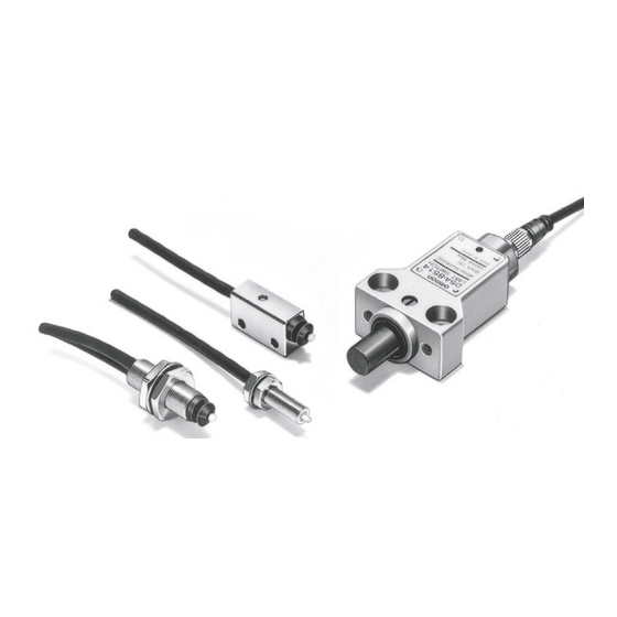
High-precision Switch
High-precision Switch for Detecting
Micron-unit Displacement
I
Ideal for detecting and measuring wear of cutting
tools or for original point of work.
I
Direct input possible to microprocessors and pro-
grammable controllers.
I
Types available with built-in operation indicator for
ease of operation monitoring as well as a version
with fiber optics remote operation indicator.
I
A version with screw-type cable connector avail-
able for easy installation and maintenance.
Application Examples
Origin Position Control of an X-Y Table
D5A
Motor
Note: Origin can be set to a desired position and the origin
position can be controlled using the D5A.
Coaxiality Inspection
D5A
Note: The D5A can be mounted on a jig used for checking
deviation to inspect its coaxiality.
Motor
D5A
Checking Turret Indexing Position
Note: Set the D5A on the turret indexing position to check if
the turret is engaged properly at the specified position.
D5A
Turret
D5A
271
Advertisement
Table of Contents

Related Manuals for Omron D5A


Summary of Contents for Omron D5A
-
Page 1: Application Examples
Turret Motor Motor Note: Origin can be set to a desired position and the origin Note: Set the D5A on the turret indexing position to check if position can be controlled using the D5A. the turret is engaged properly at the specified position. -
Page 2: Ordering Information
D5A-9512 Connector D5A-9514 D5A-9515 Specifications Ratings Contact output models 10 mA at 24 VAC, 10 mA at 12 VDC Solid-state output models 100 mA at 5 to 24 VDC – Leakage current: 0.15 mA max. Residual voltage: 3 V max. - Page 3 1. The operating position of these types is the same as the free position because of high sensitivity (repeat accuracy: 1 m max.). 2. Total movement is 1.9 to 2.1 mm. Set the appropriate stroke (plunging depth) to 1.0 to 1.5 mm from the FP.
-
Page 4: Engineering Data
820 Ω Brown (White) kΩ Blue (Black) Note: 1. HIC (hybrid integrated circuit) 2. An LED current limit resistor is incorporated. 3. The ZD absorbs surge. 4. The load can be connected to either the +V side or 0V side. - Page 5 Dimensions Note: 1. All units are in millimeters unless otherwise indicated. 2. Unless otherwise specified, a tolerance of 0.4 mm applies to all dimensions. – M5 Type (Contact Output) M5 × 0.5 S-FLEX V-HKCVV D5A-1100, D5A-2100 (see note) equal level, 3 dia.
- Page 6 (Contact Output/Solid-state Output) D5A-7403, D5A-7413 (Connector type) Note: The dimensions are the same as the above model's. Two, 4.2 dia. holes Limit Type 8 dia. spot facing depth: 5 (Solid-state Output) Nameplate D5A-8511, D5A-8512 Two, M3 × 0.5 Operation indicator (LED) 20±0.2 3 dia.
- Page 7 Do not pull or impose any force exceeding 29.42 N on the fiber Fiber cable cable. Make sure that the bending radius of the fiber cable is as large as possible and at least 25 mm. The 40-mm portion of the fiber cable on the connector end as shown below must not be bent.
- Page 8 Since the must operate voltage of the relay is 80% or less than the rated voltage, it is 12 x 0.8 = 9.6 V. The supply voltage, in turn, is 3 + 9.6 = 12.6 V.
- Page 9 No protective cover is, however, pro- vided together with the Switch. Nameplate ALL DIMENSIONS SHOWN ARE IN MILLIMETERS. To convert millimeters into inches, multiply by 0.03937. To convert grams into ounces, multiply by 0.03527. Cat. No. C070-E1-4A...
Need help?
Do you have a question about the D5A and is the answer not in the manual?
Questions and answers