Advertisement
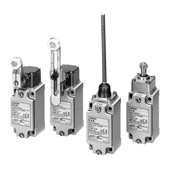
Safety Limit Switch
D4B-#N
• Snap-action or slow-action contact for
accurate switching with safe operation
via a direct opening mechanism with
metal deposition between mating con-
tacts.
• Two sets of contacts: one (NC) for safe-
ty category circuit and the other (NO)
for control circuit.
• Contacts opened by direct opening
mechanism (NC contacts only), thus
preventing faulty operation due to fac-
tors such as metal deposition.
• Wide standard operating temperature
range:
–40°C to 80°C (standard type).
• Safety of lever settings ensured using a
mechanism that engages a gear be-
tween the operating position indicator
plate and the lever.
• Equipped with a mechanism that indi-
cates the applicable operating zone, as
well as push-button switching to control
left and right motion.
• Conforms to EN (TÜV) standards cor-
responding to the CE marking.
• 3-conduit switches are available.
• Metric conduit types available.
Model Number Structure
Model Number Legend
D4B-####N
1 2
3
1. Conduit
1:
PG13.5 (1-conduit)
2:
G1/2 (PF1/2) (1-conduit)
3:
1/2-14NPT (1-conduit)
4:
M20
5:
PG13.5 (3-conduit)
6:
G1/2 (PF1/2) (3-conduit)
7:
1/2-14NPT (3-conduit)
8:
M20 (3-conduit)
2. Built-in Switch
1:
1NC/1NO (snap-action)
3:
1NC/1NO (slow-action) gold-plated contacts
5:
1NC/1NO (slow-action) (see note)
A:
2NC (slow-action)
B:
2NC (slow-action) gold-plated contacts
Note: Excluding D4B-##81N and D4B-##87N models.
D4B-@N
3. Actuator
00:
Switch box (without head)
11:
Roller lever (standard)
16:
Adjustable roller lever
17:
Adjustable rod lever
1R:
Roller lever
(conventional D4B-compatible)
70:
Top plunger
71:
Top roller plunger
81:
Coil spring
87:
Plastic rod
G-243
Advertisement
Table of Contents

Related Manuals for Omron D4B-N


Summary of Contents for Omron D4B-N
- Page 1 • Two sets of contacts: one (NC) for safe- ty category circuit and the other (NO) for control circuit. • Contacts opened by direct opening...
-
Page 2: Ordering Information
2. The D4B-#N is a Limit Switch conforming to European standards, and M20/PG13.5 is commonly used in Europe. 3. The wobble lever models are ordinary limit switches and are not approved under EN, GS, and SUVA’s Direct Opening Certificate. G-244... -
Page 3: Replacement Part
Because the D4B-#N employs a block mounting construction, the switch box, operating head, and lever (side rotary type only) may be ordered as a complete assembly or individually as replacement parts. (Replacement parts are not available as a switch box and head assembly or as a head and lever assembly.) -
Page 4: Specifications
Utilization category AC-15 Rated operating current (I Rated operating voltage (U 400 V Note: As protection against short-circuiting, use either a gI-type or gG-type 10-A fuse that conforms to IEC269. UL/CSA: (UL508, CSA C22.2 No. 14) A600 Rated voltage Carry current... -
Page 5: Operating Characteristics
2. The above values may vary depending on the model. Consult your OMRON sales representative for details. 3. The durability is for an ambient temperature of 5°C to 35°C and ambient humidity of 40% to 70%. For further conditions, consult your OMRON sales representative. - Page 6 If metal deposition between mating contacts occurs on the NC contact side, they can be pulled apart by the shearing force and tensile force gen- erated when part B of the safety cam or plunger engages part A of the movable contact blade. When the safety cam or plunger is moved in the direction of the arrow, the Limit Switch releases.
-
Page 7: Engineering Data
With roller lever models, the direction of the switch head can Grooves which engage the lever every 90∞ are cut in the be varied to any of the four directions by loosening the roller operating position indicator plate to prevent the lever from lever switch screws at the four corners of the head. - Page 8 2. Unless otherwise specified, a tolerance of ±0.4 mm applies to all dimensions. 3. When placing your order, specify the conduit type by adding a code from the list below to the blank box of the following model numbers as shown below.
- Page 9 Four, M3.5 x 7 head mounting 29.1 screws Two, 5.3-dia. mounting holes Note: Be sure to adjust the dog to within 40 mm Two, M4 x 12 cover 60±0.2 from the top end of the plastic rod. mounting screws Cover Conduit 31.5...
- Page 10 Two, caps Cover +0.15 Two, 5 -dia. holes (depth: 6) Three, Conduit Note: The lever can be set to any desired position by turning the operating position indicator. Adjustable Roller Lever D4B-##16N 19 dia. x 7 resin roller Operating posi- Four, M3.5 x 24.5 head...
- Page 11 Cover +0.15 Two, 5 -dia. holes (depth: 6) Three, Conduit Note: Set the spring so that the dog comes in contact at a point 40 mm from the tip. Plastic rod Plastic Rod D4B-##87N The Switch can be actuated to all directions except to the axis center.
- Page 12 7.3 dia. M5 hexagon 11.5 socket head screw M5 hexagon socket 11.4 head screw (length: 12) Note: Reverse the indicator plate when mounting. Note: Reverse the indicator plate when mounting. Roller Lever mechanical form lock Roller Lever Roller Lever WL-1A206 WL-1A300 WL-1A400 17.9...
- Page 13 Note: Reverse the indicator plate when mounting. Note: Reverse the indicator plate when mounting. Note: 1. Unless otherwise specified, a tolerance of ±0.4 mm applies to all dimensions. 2. Safety Limit Switch specifications are satisfied with D4B-####AN Levers only. D4B-@N...
-
Page 14: Correct Use
Precautions If the D4B-#N is applied to a safety category circuit for prevention of If an application satisfying EN standards is to employ the D4BL, injury, use the D4B-#N model that has an NC contact equipped with apply the 10-A gI or gG fuse approved by IEC269. - Page 15 1. Set the lever to operate in one direction. For details, see page G- Terminal screw 257, CW, CCW or Two-way Operation. 2. Modify the rear end of the dog to an angle of 15° to 30° as shown below or to a secondary-degree curve. θ...
- Page 16 ALL DIMENSIONS SHOWN ARE IN MILLIMETERS. To convert millimeters into inches, multiply by 0.03937. To convert grams into ounces, multiply by 0.03527. Cat. No. C005-E2-09A-X In the interest of product improvement, specifications are subject to change without notice. G-258 Safety Sensors / Components...
Need help?
Do you have a question about the D4B-N and is the answer not in the manual?
Questions and answers