
Subscribe to Our Youtube Channel
Related Manuals for Omron F3SP-U5P


Summary of Contents for Omron F3SP-U5P
- Page 1 Cat. No. E06-EN-01 F3SP-U5P-TGR Series Single Beam Safety Control Unit Safety Level 4 USER´S MANUAL...
- Page 2 F3SP-U5P-TGR User's manual Cat. No. E06-EN-01 F3SP-U5P-TGR series Single beam safety control unit, safety level 4, from 1 to 4 pairs of photocells E3FS USER'S MANUAL...
- Page 4 F3SP-U5P-TGR User's manual The device conforms with the EC requirements in compliance with the following standards: -Low Voltage Directive 73/23/EEC -EMC Directive 89/336/EEC -Machinery Directive 89/392/EEC -IEC 61496-1: 1997 -IEC 61496-2: Ed.2 IEC :2001 (CDV draft8) -DIN V VDE 0801: 1990 and...
-
Page 5: Table Of Contents
F3SP-U5P-TGR User's manual INDEX BEFORE USING THE DEVICE............5 GENERAL INSTRUCTIONS................5 PRECAUTION OF SAFETY ................5 ROUTINE MAINTENANCE................5 GENERAL INFORMATION AND MAIN APPLICATIONS....6 OPERATION..................8 PRECAUTIONS AND INSTALLATION CRITERIA......9 CALCULATION OF THE MINIMUM INSTALLATION DISTANCE.....9 REFLECTIVE SURFACES................10 CONNECTIONS................11 REFERENCES ON THE TERMINAL BOARD..........11... -
Page 6: Before Using The Device
PRECAUTION OF SAFETY The following symbols are used for highlighted items in order to ensure safe and proper use of the F3SP-U5P-TGR. Highlighted items are critical for safe operation and must be heeded at all time. WARNING NOTICE ROUTINE MAINTENANCE. -
Page 7: General Information And Main Applications
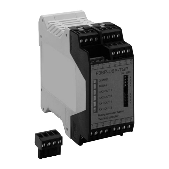
User's manual GENERAL INFORMATION AND MAIN APPLICATIONS. The single beam safety control unit F3SP-U5P-TGR has been designed and produced to meet the need to protect persons in areas where it is necessary to guarantee the safety of the operator using machinery, robots or in general automation systems which are considered dangerous or subject to casual or undesired access to unsafe parts. - Page 8 User's manual • The control unit and safety PES must not be used in water. The F3SP-U5P-TGR safety controller is protected by a plastic housing so that it can be installed on a DIN/OMEGA rail; it has 32 removable screw terminals to which it is possible to connect from 1 to 4 pairs of photocells.
-
Page 9: Operation
F3SP-U5P-TGR User's manual OPERATION. The electronic control system of the device is made up of a microprocessor. By means of the suitable hardware, it continuously control and check the connected photocells. No interference among the photocells is possible as they are controlled sequentially; it will be thus possible to install one or two adjacent photocells. -
Page 10: Precautions And Installation Criteria
F3SP-U5P-TGR User's manual PRECAUTIONS AND INSTALLATION CRITERIA. The safety products used must be suitable for the required application, and other influences must be also taken into account such as a room temperature, electromagnetic interference, intense light sources etc. Please refer to the manual for specification or contact the manufacturer for details. -
Page 11: Reflective Surfaces
F3SP-U5P-TGR User's manual WARNING. Always maintain the safety distance between the safety PES and a hazardous part of a machine. REFLECTIVE SURFACES. In case that reflective surface exist, the distance must be sufficient to avoid the possibility of passive reflections. -
Page 12: Connections
F3SP-U5P-TGR User's manual Do not install the safety PES in a location affected by shiny surface reflections. CONNECTIONS. REFERENCES ON THE TERMINAL BOARD. TERMINAL BLOCK ASSIGNMENT TERMINAL OUTER CONNECTION Connect to the 24 Vdc power supply, terminal 1 24Vdc / terminal 2 0Vdc. -
Page 13: Pinout Top View
F3SP-U5P-TGR User's manual PINOUT TOP VIEW BREAK / GUARD FTC.4 FTC.3 FTC.2 FTC. 1... -
Page 14: Wiring Example
F39-A11 Safety output 2 EXTERNAL FUSE Top view 9 10 11 12 13 14 15 16 F3SP-U5P-TGR PIN Assignment 17 18 19 20 21 22 23 24 25 26 27 28 29 30 31 32 bleu black bleu black brown... - Page 15 F3SP-U5P-TGR User's manual Please, note: • To configure the control unit in such a way that it works only with three photocells, it is necessary to connect the unused transmitter output to the corresponding receiver input, in this case to terminal TEST-TX3 with PNP_OUT-RX3.
-
Page 16: Alignment Procedure
F3SP-U5P-TGR User's manual ALIGNMENT PROCEDURE. After having carried out the correct mechanical assembly and the correct connections as described in the previous paragraphs, it is necessary to align the pairs of photocells. Follow the operative modes as follows: • Turn off the power supplying the control unit. -
Page 17: Operating Procedures
F3SP-U5P-TGR User's manual OPERATING PROCEDURES. DIP-SWITCHES CONFIGURATION. The configuration indicated in the table must be selected on both the dip- switches available in the front cover. SW 1 SW 2 Function not used Function muting A-B act on the sensor couples 1 and 2. -
Page 18: Muting Function
It is important to note that if the muting indicator is connected during the F3SP-U5P-TGR is powered on, it will not be recognised and the muting function will not be enabled. Once enabled, if the indicator develops a fault or is removed without first disconnecting the unit’s power... -
Page 19: Installation Criteria
1 and 2, preventing package 3 from passing. The protection photocells S are connected to the F3SP-U5P-TGR control unit and are temporarily interrupted at the package passage by means of the muting A1, A2, B1 and B2 activated sensors. - Page 20 F3SP-U5P-TGR User's manual Application with four muting sensors, passage permitted only for package 1: Muting sensor connection: 24 V contact of A1 N.C. 11 MUTE C 10 MUTE D N.C. contact of A2 9 MUTE A 8 MUTE B contact of B1...
- Page 21 F3SP-U5P-TGR User's manual where: minimum distance that the muting sensors keep active the request; it depends on the parcel length: D < L. necessary maximum distance so that the muting request is accepted; it depends on the parcel speed: [cm]= v[m/s] * 3[s] * 100 This distance must not allow to activate both sensors and the muting with the accidental passage of a person.
- Page 22 F3SP-U5P-TGR User's manual Muting sensor connection: 24 V contact of A1 11 MUTE C N.C. 10 MUTE D N.C. contact of A2 9 MUTE A 8 MUTE B contact of B1 F3SP-U5P-TGR terminals contact of B2 The examples above are thought for the use of the muting functions only relating to sensors S1 and S2, with the configuration DIP-SWITCH 2 in the off positions;...
- Page 23 F3SP-U5P-TGR User's manual Muting sensor connection: 24 V Muting enable to S3 and S4 from robot system control contact of A3 contact of A4 contact of B3 11 MUTE C contact of B4 10 MUTE D 9 MUTE A contact of A1...
-
Page 24: Override
F3SP-U5P-TGR User's manual OVERRIDE. This function makes it possible to force a muting condition, if it is necessary to start the machine despite one or more rays have been interrupted by the material. The aim is that of removing from the protected area the material which has possibly gathered before the photocells for instance because of a failure of the machine cycle. -
Page 25: Muting Restrictions (Muting Function)
F3SP-U5P-TGR User's manual MUTING RESTRICTIONS (muting function). a) The muting operation must occur according to the correct timing sequence. For the two muting channels, it is necessary to activate input MUTE_A or MUTE_C at first and then input MUTE_B or MUTE_D within 3 seconds. -
Page 26: Led Diagnostic
F3SP-U5P-TGR User's manual LED DIAGNOSTIC Information of the units operative state by means of four LEDs. The LED state has the following meaning: • GREEN LEDs: if switched on, the photocells work regularly and no object is detected; the relays are closed. -
Page 27: Final Checks
F3SP-U5P-TGR User's manual FINAL CHECKS. Check that the area protected by the barrier is free from any obstacle; check the correct triggering of the safety relay opening by interrupting the protection rays (red LED switched on, controlled machine stopped). CAUTION! If the red LED switches on and off, check the correct mechanical assembly. -
Page 28: General Information And Useful Data
F3SP-U5P-TGR User's manual 11 GENERAL INFORMATION AND USEFUL DATA. Safety MUST be part of our consciousness. The safety devices are useful only if installed correctly by respecting the indications reported on the standards. If you believe not to have the sufficient competence to correctly install the safety devices apply to our advisory service or request the installation. -
Page 29: Technical Data
12 TECHNICAL DATA. • Voltage: 24 Vdc ± 10% • Electrical input: 420 mA max (for any model) • Combinable photocells: OMRON E3FS series and Techno GR S5 – S10 – S30 series • Number of photocells: four pairs max •... -
Page 30: Overall Dimensions
F3SP-U5P-TGR User's manual 13 OVERALL DIMENSIONS. Control unit F3SP-U5P-TGR... -
Page 31: Note
F3SP-U5P-TGR User's manual 14 NOTE... - Page 33 MANUFACTURER TECHNO-GR s.r.l. Via Torino, 13/15 10046 Poirino (TO) ITALY Tel: +39-011-9452041 / FAX: +39-011-9452090 GENERAL AGENCY OMRON EUROPE B.V. SENSOR BUSINNES UNIT Carl-Benz-Str. 4 71154 Nufringen GERMANY Tel : -49-7032-811-0 / FAX : -49-7032-811-199 Authorized distributor : Cat. E06-E-01 Note: Specification subject to change without notice Par.
Need help?
Do you have a question about the F3SP-U5P and is the answer not in the manual?
Questions and answers