
Related Manuals for Omron SYSDRIVE 3G3FV-*-CUE


Summary of Contents for Omron SYSDRIVE 3G3FV-*-CUE
- Page 1 Cat. No. I530-E1-1 INSTALLATION MANUAL SYSDRIVE 3G3FV-j-CUE/3G3HV-j-CUE (-CE) (Models Conforming to CE and UL/cUL Standards) www.dadehpardazan.ir 88594014-15...
- Page 2 :ﺗﻮﻟﯿﺪ ﮐﻨﻨﺪه اﻧﻮاع ﻣﺤﺼﻮﻻت اﺗﻮﻣﺎﺳﯿﻮن ﺻﻨﻌﺘﯽ ﺷﺮﮐﺖ ﺑﯿﻦ اﻟﻤﻠﻠﯽ Omron ) ﮐﻨﺘﺮل ﮐﻨﻨﺪه ﻫﺎي ﻣﻨﻄﻘﯽ ﻧﻤﺎﯾﺸﮕﺮﻫﺎي ﺻﻨﻌﺘﯽ ) ﮐﺎﻣﭙﯿﻮﺗﺮﻫﺎي ﺻﻨﻌﺘﯽ ) ﺳﯿﺴﺘﻢ ﻫﺎي ﺟﻤﻊ آوري اﻃﻼﻋﺎت Data Logger ... ﺳﻨﺴﻮرﻫﺎي ﺻﻨﻌﺘﯽ ﺟﻬﺖ اﻧﺪازه ﮔﯿﺮي ﻃﻮل، ﺿﺨﺎﻣﺖ و ) ﺳﯿﺴﺘﻢ ﻫﺎي ﭘﺮدازش ﺗﺼﻮﯾﺮ...
- Page 3 You should assume that anything not described in this manual is not possible. 2. Although care has been given in documenting the product, please contact your OMRON representative if you have any suggestions on improving this manual. 3. The product contains potentially dangerous parts under the cover. Do not attempt to open the cover under any circumstances.
- Page 4 OMRON. No patent liability is assumed with respect to the use of the information contained herein. Moreover, because OMRON is constantly striving to improve its high-quality products, the information contained in this manual is subject to change without notice.
-
Page 5: Wiring Precautions
Transportation Precautions Caution Do not hold by front cover or panel , instead, hold by the radiation fin (heat sink) while transporting the product. Doing so may result in injury. Caution Do not pull on the cables. Doing so may result in damage to the product or malfunc- tion. - Page 6 Caution Install external breakers and take other safety measures against short-circuiting in external wiring. Not doing so may result in fire. Caution Confirm that the rated input voltage of the Inverter is the same as the AC power sup- ply voltage. An incorrect power supply may result in fire, injury, or malfunction. Caution Connect the Braking Resistor and Braking Resistor Unit as specified in the manual.
- Page 7 Make sure that these protective covers are on the product before use. Consult your OMRON representative when using the product after a long period of storage. WARNING Do not touch the inside of the Inverter. Doing so may result in electrical shock.
- Page 8 WARNING Be sure confirm that the RUN signal is turned OFF before turning ON the power supply, resetting the alarm, or switching the LOCAL/REMOTE selector. Doing so while the RUN signal is turned ON may result in injury. Caution Be sure to confirm permissible ranges of motors and machines before operation because the Inverter speed can be easily changed from low to high.
- Page 9 Warnings for UL/cUL Marking - Do not connect or disconnect wiring, or perform signal checks while the power supply is turned ON. - The Inverter internal capacitor is still charged even after the power supply is turned OFF. To prevent electrical shock, disconnect all power before servicing the Inverter.
- Page 10 Warning Label A warning label is attached to the product as shown in the following illustration. Be sure to observe the precautionary items specified on the label. Warning label Contents of Warning Label www.dadehpardazan.ir 88594014-15...
- Page 11 www.dadehpardazan.ir 88594014-15...
-
Page 12: Table Of Contents
Table of Contents Chapter 1. Introduction ........1-1 Function . - Page 13 www.dadehpardazan.ir 88594014-15...
-
Page 14: Chapter 1. Introduction
Chapter 1 Introduction Function Nomenclature www.dadehpardazan.ir 88594014-15... - Page 15 Chapter 1 Introduction Function H SYSDRIVE 3G3FV-j-CUE/3G3HV-j-CUE (-CE) Inverter Models (Models Conforming to CE and UL/cUL Standards) • SYSDRIVE Inverter models include the 3G3FV Series and 3G3HV Series that conform to the CE mark and UL mark. • The maximum applied motor capacity ranges from 0.4 kW to 160 kW (18 models). D 3G3FV Series Voltage class Protective structure...
- Page 16 Chapter 1 Introduction D 3G3HV Series Voltage class Protective structure Maximum applied motor capacity Model 200-V class NEMA1 type 0.4 kW 3G3HV-AB004-CE (single phase) 0.75 kW 3G3HV-AB007-CE 1.5 kW 3G3HV-AB015-CE 2.2 kW 3G3HV-AB022-CE 3.7 kW 3G3HV-AB037-CE 400-V class NEMA1 type 0.4 kW 3G3HV-A4004-CUE (3-phase)
-
Page 17: Other Functions
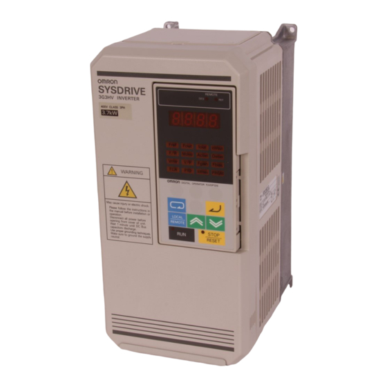
Chapter 1 Introduction H UL/cUL Standards SYSDRIVE models described here as “Models Conforming to CE and UL/cUL Standards” have ob- tained approval on the UL/cUL Standard (UL508C) in addition to the EC Directives. The SYSDRIVE models meeting these standards can be used worldwide. H Other Functions Although this manual describes the installation methods for conforming to the LVD and EMC Directives, it does not describe the standard functions of the Inverter. - Page 18 Chapter 1 Introduction Nomenclature H Panel Protection cover (top and bottom) Mounting hole Heat sink Digital Operator Front cover Terminals Front cover fixing bracket 3G3FV Series www.dadehpardazan.ir 88594014-15...
- Page 19 Chapter 1 Introduction D Terminals (with Front Cover Removed) 3G3FV Series: 400-V Class Inverter with 3.7-kW Output Control circuit terminals Main circuit terminals 3G3HV Series: 400-V Class Inverter with 3.7-kW Output Control circuit terminals Main circuit terminals www.dadehpardazan.ir 88594014-15...
-
Page 20: Chapter 2. Installation
Chapter 2 Installation Mounting Wiring www.dadehpardazan.ir 88594014-15... -
Page 21: Mounting
Chapter 2 Installation Mounting 2-1-1 Dimensions H 3G3FV-A4004-CUE/-A4007-CUE/-A4015-CUE/-A4022-CUE/-A4037-CUE 3G3HV-AB004-CE/-AB007-CE/-AB015-CE/-A4004-CUE/-A4007-CUE 3G3HV-A4015-CUE/-A4022-CUE/-A4037-CUE D External Dimensions D Mounting Dimensions Two, 5.5 dia. Four, M5 Dimensions (mm) Series Voltage class Model 3G3FV-/3G3HV- 3G3FV 400-V A4004-CUE/A4007-CUE A4015-CUE/A4022-CUE/A4037-CUE 180 3G3HV 200-V (single phase) AB004-CE AB007-CE/AB015-CE 400-V A4004-CUE/A4007-CUE A4015-CUE/A4022-CUE/A4037-CUE 180 www.dadehpardazan.ir 88594014-15... - Page 22 Chapter 2 Installation H 3G3FV-A4055-CUE/-A4075-CUE 3G3HV-AB022-CE/-AB037-CE/-A4055-CUE/-A4075-CUE D External Dimensions D Mounting Dimensions Four, M6 Two, 7 dia. H 3G3FV-A4110-CUE/-A4150-CUE 3G3HV-A4110-CUE/-A4150-CUE D External Dimensions D Mounting Dimensions Two, 7 dia. Four, M6 www.dadehpardazan.ir 88594014-15...
- Page 23 Chapter 2 Installation H 3G3FV-B4185-CUE/-B4220-CUE/-B4300-CUE/-B4450-CUE 3G3HV-B4185-CUE/-B4220-CUE/-B4300-CUE/-B4450-CUE D External Dimensions D Mounting Dimensions Four, M6 Series Voltage class Model 3G3FV-/3G3HV- Dimensions (mm) 3G3FV 400-V B4185-CUE/B4220-CUE 174.5 B4300-CUE/B4370-CUE/B4450-CUE 3G3HV 400-V B4185-CUE/B4220-CUE 174.5 B4300-CUE/B4370-CUE/B4450-CUE www.dadehpardazan.ir 88594014-15...
- Page 24 Chapter 2 Installation H 3G3FV-B4550-CUE/-B4750-CUE 3G3HV-B4550-CUE/-B4750-CUE D External Dimensions D Mounting Dimensions Two, 12 dia. Four, M10 www.dadehpardazan.ir 88594014-15...
- Page 25 Chapter 2 Installation H 3G3FV-B411K-CUE/-B416K-CUE 3G3HV-B411K-CUE/-B416K-CUE D External Dimensions D Mounting Dimensions Two, 14 dia. Four, M12 Dimensions (mm) Series Voltage class Model 3G3FV-/3G3HV- 3G3FV 400-V B411K-CUE B416K-CUE 3G3HV 400-V B411K-CUE B416K-CUE www.dadehpardazan.ir 88594014-15...
-
Page 26: Installation Conditions
Chapter 2 Installation 2-1-2 Installation Conditions H Installation Precautions WARNING Provide an appropriate stopping device on the machine side to secure safety. (A holding brake is not a stopping device for securing safety.) Not doing so may result in injury. WARNING Provide an external emergency stopping device that allows an instantaneous stop of operation and power interruption. - Page 27 Chapter 2 Installation H Installation Site • Install the Inverter under the following conditions. NEMA1 Type Ambient temperature for operation: –10°C to 40°C Humidity: 90% RH or less (no condensation) Open Chassis Type Ambient temperature for operation: –10°C to 45°C Humidity: 90% RH or less (no condensation) Note Remove the top and bottom covers when using the open chassis type of 15 kW or less.
-
Page 28: Wiring
Chapter 2 Installation Wiring WARNING Wiring must be performed only after confirming that the power supply has been turned OFF. Not doing so may result in electrical shock. WARNING Wiring must be performed by authorized personnel. Not doing so may result in electrical shock or fire. -
Page 29: Removing And Mounting The Front Cover . . . . . . . . . . . . . . . . . . . . . . . . . . . . . . . . . . 2-2-2 Terminals
Chapter 2 Installation 2-2-1 Removing and Mounting the Front Cover Remove the front cover to wire the terminals. Remove the Digital Operator from the front cover before removing the front cover. For models of 15 kW or less (both 200-V and 400-V class), do not remove or mount the front cover without first removing the Digital Operator;... - Page 30 Chapter 2 Installation 2. While pressing the sides of the front cover, pull the front cover towards you. • Mounting the Front Cover Mount the front cover to the Inverter by taking in reverse order to the steps to remove the front cover after wiring the terminals.
- Page 31 Chapter 2 Installation H Mounting the Digital Operator • Hook the Digital Operator on clicks A of the front cover in the arrow 1 direction as shown in the follow- ing illustration. • Press the Digital Operator in the arrow 2 direction until it snaps shut with clicks B. Clicks A Clicks B Note Do not remove or attach the Digital Operator or mount or remove the front cover using methods...
- Page 32 Chapter 2 Installation 2-2-2 Terminals H 3G3FV Series D Terminal Block Configuration (400-V Class with 3.7-kW Output, CUE Models) Control circuit terminals Main circuit terminals D Main Circuit Terminals Voltage class 400-V class A4004 to A4150 B4185 to B4450 B4550 to B416K Model 3G3FV-j-CUE Maximum applied motor 0.4 to 15 kW...
- Page 33 Chapter 2 Installation Note 1. These are the cooling fan power supply and control circuit power supply input terminals. Note 2. When 200 V is used, input 200 to 230 VAC from r – s200. When 400 V is used, input 380 to 460 VAC from r –...
- Page 34 Chapter 2 Installation Symbol Name Function Signal level Set by parameter H2-01 (during running). Contact output Multi-function contact output (NO con- quence dition) (SPST-NO) output 30 VDC, 1 A max. Multi-function contact output common 250 VAC, 1 A max. Multi-function output 1 Set by parameter H2-02 (zero speed Open collector out- detection).
- Page 35 Chapter 2 Installation D Main Circuit Terminals Voltage class 200-V class 400-V class AB004 to AB037 A4004 to A4150 B4185 to B416K Model 3G3HV-j-CUE (-CE) Maximum 0.4 to 3.7 kW 0.4 to 15 kW 18.5 to 160 kW applied motor capacity L (R) Power supply input...
- Page 36 Chapter 2 Installation D Control Circuit Terminals for All 3G3HV-j-CUE Models Symbol Name Function (see note) Signal level Forward run/Stop Stops at OFF. Photocoupler quence S2 24 VDC, 8 mA Multi-function input 1 (S2) Set by constant n035 (reverse run/stop). input Multi-function input 2 (S3) Set by constant n036 (external error a).
-
Page 37: Standard Connection Diagram
Chapter 2 Installation 2-2-3 Standard Connection Diagram H Main Circuit Terminal Connections D 3G3FV Model 3G3FV-A4004 to A4150 DC reactor (optional) Braking Resistor Unit (optional) 3-phase 400 VAC Shield Noise filter Shield Fuse Three-phase L1 (R) T1 (U) induction motor L2 (S) T2 (V) L3 (T) - Page 38 Chapter 2 Installation 3G3FV-B4550 to B416K Braking Resistor Unit (optional) Braking Unit (optional) 3-phase 400 VAC Shield Noise filter Fuse Shield Three-phase L1 (R) induction motor T1 (U) L2 (S) T2 (V) L3 (T) T3 (W) Note 1. The DC reactor is built in. Note 2.
- Page 39 Chapter 2 Installation Note 1. Be sure to remove the short bar before connecting a DC reactor. Note 2. The R1 (L11)-R (1),S1 (L21)-S (L2), and T1(L31)-T(L3) terminals are short-circuited for ship- ping. General Notes Note 1. The Braking Unit and Braking Resistor Unit cannot be connected to the 3G3HV Inverters of 18.5 kW to 160 kW.
- Page 40 Chapter 2 Installation D 3G3HV Model Forward run/stop Multi-function Multi-function analog contact input 1 output Multi-function contact input 2 Voltmeter Multi-function contact input 3 Multi-function analog Multi-function output common contact input 4 Multi-function contact input 5 Multi-function contact Sequence input common output 1 (NO) Multi-function contact output 1 (NC)
- Page 41 Chapter 2 Installation D When Using a NPN Transistor (Open Collector) for Control Signals (See note) 36/SP 35/SS 11/SC 1/S1 Forward/stop Note Numeric characters indicate terminal numbers for the 3G3FV and alphanumeric characters indi- cate terminal numbers for the 3G3HV. 2-22 www.dadehpardazan.ir 88594014-15...
-
Page 42: Wiring Around The Main Circuit
Chapter 2 Installation 2-2-4 Wiring Around the Main Circuit System reliability and noise resistance are affected by the wiring method used. There- fore, always follow the instructions given below when connecting the Inverter to periph- eral devices and other parts. H Wire Size and Round Solderless Terminal D Wire Sizes Model... - Page 43 Chapter 2 Installation Model Terminal Terminal Wire 3G3FV-j-CUE/ screw thickness 3G3HV-j-CUE B4450 L1, L2, L3, L11, L21, L31, (–), (+)1, (+)2, (+)3, U, V, W 0.5 to 5.5 B4550 L1, L2, L3, L11, L21, L31, (–), (+)3, U, V, W 0.5 to 5.5 200, 60 ×...
- Page 44 Chapter 2 Installation D Round Solderless Terminals and Tightening Torque Wire thickness Terminal Size Tightening screw torque (NSm) M3.5 1.25 – 3.5 1.25 – 4 0.75 M3.5 1.25 – 3.5 1.25 – 4 1.25 M3.5 1.25 – 3.5 1.25 – 4 M3.5 2 –...
- Page 45 Chapter 2 Installation H Conformance to EMC Directives In order to conform to EMC Directives, the exclusive-use methods are required for noise filter applica- tion, cable shielding, and Inverter installation. The following provides an outline of the methods. The noise filter and the Inverter must be mounted on the same metal plate. The filter should be mounted as close to the Inverter as practical.
- Page 46 Chapter 2 Installation D 3G3FV-A4004 to A4150, 3G3HV-A4004 to A4150 Installation of Noise Filter and Inverter Ground bonds (remove any paint.) Mains Filter Load Cable length: 40 cm max. Metal plate Ground bonds (remove any paint.) Motor cable: 20 m max. 2-27 www.dadehpardazan.ir 88594014-15...
- Page 47 Chapter 2 Installation D 3G3FV-B4185 to B416K, 3G3HV-B4185 to B416K Installation of Noise Filter and Inverter Ground bonds (remove any paint.) Mains Filter Load Cable length: 40 cm max. Metal plate Ground bonds (remove any paint.) Motor cable: 20 m max. 2-28 www.dadehpardazan.ir 88594014-15...
- Page 48 Chapter 2 Installation D 3G3HV-AB004 to AB037 Installation of Noise Filter and Inverter Ground bonds (remove any paint.) Mains Filter Load Cable length: 40 cm max. Metal plate Ground bonds (remove any paint.) Motor cable: 20 m max. 2-29 www.dadehpardazan.ir 88594014-15...
- Page 49 Chapter 2 Installation H Conformance to Low-voltage Directives An input fuse is not provided with the SYSDRIVE Inverter. Make sure to connect the fuses between the AC main circuit power supply and Inverter input terminals L1, L2 and L3 to protect the input diode or cables.
- Page 50 Chapter 2 Installation Input Fuse Selection Note Both input diodes and cables can be protected by selecting appropriate fuses shown in the follow- ing tables. D 400-V Class Inverter Fuse Max. Rated input Rated t max. Manufacturer Type 12-pulse applicable current (A) current input (see...
- Page 51 Chapter 2 Installation H Wiring on the Input Side of Main Circuit D Installing a Molded-case Circuit Breaker Provide fuses recommended for each Inverter between the power supply and the power input terminals (L1, L2, and L3). It is recommended that a molded case circuit breaker (MCCB) that matches the Invert- er be provided between the power supply and the input terminals to facilitate easy operation and main- tenance.
- Page 52 Chapter 2 Installation D Installing a Magnetic Contactor If the power supply for the main circuit is to be shut off because of the sequence, a magnetic contactor can be used instead of a molded-case circuit breaker. When a magnetic contactor is installed on the primary side of the main circuit to forcibly stop a load, however, the regenerative braking does not work and the load coasts to a stop.
- Page 53 Chapter 2 Installation H Wiring on the Output Side of Main Circuit D Connecting the Terminal Block to the Load Connect output terminals T1 (U), T2 (V), and T3 (W) to motor lead wires T1 (U), T2 (V), and T3 (W), respectively.
- Page 54 Chapter 2 Installation Induction Noise: Electromagnetic induction generates noise on the signal line, causing the controller to malfunction. Radio Noise: Electromagnetic waves from the Inverter and cables cause the broadcasting radio receiver to make noise. D Cable Length between Inverter and Motor As the cable length between the Inverter and the motor is increased, the floating capacity between the Inverter outputs and the ground is increased proportionally.
- Page 55 Chapter 2 Installation H Ground Wiring • Connect the ground terminal to the supply neutral (neutral point of the input power supply). • Always use the ground terminal of the 200-V Inverter with a ground resistance of less than 100 Ω and that of the 400-V Inverter with a ground resistance of less than 10 Ω.
- Page 56 Chapter 2 Installation H Countermeasures against Harmonics With the continuing development of electronics, the generation of harmonics from industrial machines has been causing problems recently. Refer to the following for the definition of harmonics (i.e., harmonic currents with voltages) and countermeasures against the generation of harmonics from the Inverter. D Harmonics (Harmonic Currents with Voltages) •...
- Page 57 Chapter 2 Installation • Inverter The Inverter as well as normal electric machines has an input current containing harmonics because the Inverter converts AC into DC. The output current of the Inverter is comparatively high. Therefore, the ratio of harmonics in the output current of the Inverter is higher than that of any other electric machine.
- Page 58 Chapter 2 Installation • Wiring Method With DC Reactor DC reactor (optional) 200 VAC (400 V) L1 (R) T1 (U) L2 (S) T2 (V) L3 (T) T3 (W) 3G3HV Note Be sure to remove the short bar on terminals +1 and +2 before connecting the DC reactor. With DC and AC Reactors DC reactor (optional)
- Page 59 Chapter 2 Installation D Countermeasures with 12-pulse Rectification against Harmonics Generation (Only for 3G3HV Models Larger than 18.5 kW) • 12-pulse Rectification The 3G3HV-series Inverter with an output of 18.5 to 160 kW can employ 12-pulse rectification, which suppresses harmonics better than reactors. The 3G3HV-series Inverter with an output of 15 kW or less cannot employ 12-pulse rectification.
- Page 60 Chapter 2 Installation • Input Transformers for 12-pulse Rectification Refer to the following table to select the input transformer for 12-pulse rectification. Refer to the mini- mum currents on the secondary winding side in the table when selecting two standard transformers used in combination for 12-pulse rectification.
- Page 61 Chapter 2 Installation H Connecting the Braking Resistor Unit and Braking Unit • Connect the Braking Resistor Unit and Braking Unit to the Inverter as shown in the following diagrams. • For the 3G3FV, set L8-01 to “0” (i.e., no overheating protection of the braking resistor) and L3-04 to “0” (i.e., no decelerating stall prevention) or “2”...
- Page 62 Chapter 2 Installation D Connecting Braking Units in Parallel When connecting two or more Braking Units in parallel, use the wiring and connectors shown in the following diagram. There are connectors for selecting whether each Braking Unit is to be a Master or Slave.
-
Page 63: Wiring Control Circuit Terminals
Chapter 2 Installation 2-2-5 Wiring Control Circuit Terminals A control signal line must be 50 m maximum and separated from power lines. The fre- quency reference must be input to the Inverter through twisted-pair wires. H Wire Size and Round Solderless Terminals Use thick wires to prevent voltage drops if the wires are long. - Page 64 Chapter 2 Installation H Wiring Control Circuit Terminals D Wiring Method 1. Loosen the terminal screws with a thin-slotted screwdriver. 2. Insert the wires from underneath the terminal block. 3. Tighten the terminal screws firmly. Note 1. Always separate the control signal line from the main circuit cables and other power cables. Note 2.
- Page 65 www.dadehpardazan.ir 88594014-15...
-
Page 66: Chapter 3. Specifications
Chapter 3 Specifications Inverter Specifications Input Noise Filter Specification www.dadehpardazan.ir 88594014-15... -
Page 67: Inverter Specifications
Chapter 3 Specifications Inverter Specifications General Specifications for 3G3FV Inverters Model number A4004 A4007 A4015 A4022 A4037 A4055 A4075 A4110 A4150 B4185 B4220 B4300 B4370 B4450 B4550 B4750 B411K B416K 3G3FV-j-CUE Max. applicable motor capac- 0.75 18.5 ity (kW) Output characteristics Rated output capacity (kVA) Rated output current (A) - Page 68 Chapter 3 Specifications Protective Functions Model number A4004 A4007 A4015 A4022 A4037 A4055 A4075 A4110 A4150 B4185 B4220 B4300 B4370 B4450 B4550 B4750 B411K B416K 3G3FV-j-CUE Motor protection Protection by electronic thermal. Instantaneous overcurrent Stops at approx. 200% of rated output current. protection Overload protection Stops in one minute at approx.
- Page 69 Chapter 3 Specifications General Specifications for 3G3HV Inverters D 200-V Class Model AB004 AB007 AB015 AB022 AB037 3G3HV-j-CE Maximum applica- 0.75 ble motor capacity (kW) Output characteristics Rated output capacity (kVA) Rated output 17.5 current (A) Maximum out- 3-phase, 200 to 230 VAC put voltage (V) (Corresponds to input voltage.) Maximum out-...
- Page 70 Chapter 3 Specifications Control Characteristics Model AB004 AB007 AB015 AB022 AB037 3G3HV-j-CUE (-CE) A4004 A4007 A4015 A4022 A4037 A4055 A4075 A4110 A4150 B4185 B4220 B4300 B4370 B4450 B4550 B4750 B411K B416K Power supply har- DC reactor connection possible. Built-in DC reactor monic countermea- 12-phase rectification input sures...
-
Page 71: Input Noise Filter Specification
Chapter 3 Specifications Input Noise Filter Specification Noise Filter List for EMC Directives Noise filter (manufactured by Schaffner) Inverter model 3G3FV/3G3HV Model Rated current (A) Weight (kg) Dimensions (W×D×H) (mm) 3G3FV-PFS4874-7-07 50×126×255 A4004-CUE A4007-CUE A4015-CUE 3G3FV-PFS4874-18-07 55×142×305 A4022-CUE A4037-CUE 3G3FV-PFS4874-30-07 60×150×335 A4055-CUE A4075-CUE... - Page 72 Chapter 3 Specifications External Dimensions of Input Noise Filters D 3G3FV-PFS4874-7-07 to PFS4874-55-07 Model 3G3FV- PFS4874-7-07 300±10 PFS4874-18-07 300±10 PFS4874-30-07 400±10 PFS4874-42-07 500±10 PFS4874-55-07 500±10 www.dadehpardazan.ir 88594014-15...
- Page 73 Chapter 3 Specifications D 3G3FV-PFS4874-75-34 to PFS4874-130-35 Model 3G3FV- PFS4874-75-34 PFS4874-100-35 PFS4874-130-35 www.dadehpardazan.ir 88594014-15...
- Page 74 Chapter 3 Specifications D 3G3FV-PFS4874-180-07 D 3G3FV-PFS4874-300-99/PFS4874-400-99 9 dia. × 6 M12 × 2 d dia. × 6 Model 3G3FV- PFS4874-300-99 PFS4874-400-99 10.5 www.dadehpardazan.ir 88594014-15...
- Page 75 Chapter 3 Specifications D 3G3HV-PFS4971-10-07 for Single-phase 200-V Class (0.4 kW) Two, 5.3 × 6 oval holes D 3G3HV-PFS4971-20-07 for Single-phase 200-V Class (0.75 and 1.5 kW) Three, 4.4 × 7.4 oval holes 3-10 www.dadehpardazan.ir 88594014-15...
- Page 76 Chapter 3 Specifications D 3G3HV-PFS4971-40-07 for Single-phase 200-V Class (2.2 and 3.7 kW) Four, 5.3 × 7 oval holes 3-11 www.dadehpardazan.ir 88594014-15...
-
Page 77: Revision History
Revision History A manual revision code appears as a suffix to the catalog number on the front cover of the manual. Cat. No. I530-E1-1 Revision code The following table outlines the changes made to the manual during each revision. Page numbers refer to the previous version. - Page 78 :ﺗﻮﻟﯿﺪ ﮐﻨﻨﺪه اﻧﻮاع ﻣﺤﺼﻮﻻت اﺗﻮﻣﺎﺳﯿﻮن ﺻﻨﻌﺘﯽ ﺷﺮﮐﺖ ﺑﯿﻦ اﻟﻤﻠﻠﯽ Omron ) ﮐﻨﺘﺮل ﮐﻨﻨﺪه ﻫﺎي ﻣﻨﻄﻘﯽ ﻧﻤﺎﯾﺸﮕﺮﻫﺎي ﺻﻨﻌﺘﯽ ) ﮐﺎﻣﭙﯿﻮﺗﺮﻫﺎي ﺻﻨﻌﺘﯽ ) ﺳﯿﺴﺘﻢ ﻫﺎي ﺟﻤﻊ آوري اﻃﻼﻋﺎت Data Logger ... ﺳﻨﺴﻮرﻫﺎي ﺻﻨﻌﺘﯽ ﺟﻬﺖ اﻧﺪازه ﮔﯿﺮي ﻃﻮل، ﺿﺨﺎﻣﺖ و ) ﺳﯿﺴﺘﻢ ﻫﺎي ﭘﺮدازش ﺗﺼﻮﯾﺮ...
Need help?
Do you have a question about the SYSDRIVE 3G3FV-*-CUE and is the answer not in the manual?
Questions and answers