Table of Contents
Advertisement
Quick Links
New Product
Digital Temperature Controller (Simple Type)
E5CD-800/E5ED-800
Next Generation Digital Temperature Controllers
E5CD-800 (48 × 48 mm) and E5ED-800 (48 × 96 mm)
Lineup of Push-In Plus technology that reduce wiring
work.
E5CD-B-800 (48 × 48 mm) and E5ED-B-800 (48 × 96 mm)
Optimize Control by Detecting Status Changes.
Easily Satisfy Both Productivity and Quality.
48 × 48 mm
E5CD-800/E5CD-B-800
Accurately Measure Seal Temperatures
Temperature Sensors for Packaging Machines
48 × 96 mm
E5ED-800/E5ED-B-800
Temperature Sensors
E52
Ferrule terminal type added
1
Advertisement
Table of Contents

Related Manuals for Omron E5CD-B-800 Series


Summary of Contents for Omron E5CD-B-800 Series
- Page 1 New Product Digital Temperature Controller (Simple Type) E5CD-800/E5ED-800 Next Generation Digital Temperature Controllers E5CD-800 (48 × 48 mm) and E5ED-800 (48 × 96 mm) Lineup of Push-In Plus technology that reduce wiring work. E5CD-B-800 (48 × 48 mm) and E5ED-B-800 (48 × 96 mm) Optimize Control by Detecting Status Changes.
- Page 2 Automatic Filter Adjustment). For the most recent information on models that have been • Function specialized for water-cooled extruders (Water- certified for safety standards, refer to your OMRON website. cooling Output Adjustment). • Indication data (Power ON Time, Ambient Temperature, and Refer to Safety Precautions on 43.
-
Page 3: Model Number Legend
E5CD-800/E5CD-B-800 Model Number Legend and Standard Models Model Number Legend Models with Screw Terminal Blocks E5CD-@@ 2 @ D M -@@@ (Example: E5CD-RX2ADM-800) −− − − − − −−− B C D E No. of Power Model Meaning Control outputs Terminal Input auxiliary... - Page 4 E5CD-800/E5CD-B-800 Model Number Legend Models with Push-In Plus Terminal Blocks E5CD-@@ 2 @ B M -@@@ (Example: E5CD-RX2ABM-800) −− − − − − −−− B C D E No. of Power Model Meaning Control outputs Terminal Input auxiliary supply Options 1 and 2 type type...
- Page 5 E5CD-800/E5CD-B-800 Optional Products (Order Separately) Terminal Covers Front Covers (Cannot be used on a Push-In Plus terminal block type) Type Model Model Hard Front Cover Y92A-48H E53-COV17 Soft Front Cover Y92A-48D E53-COV23 (3pcs) Draw-out Jig Note: The E53-COV10 cannot be used. (Cannot be used on a Push-In Plus terminal block type) Refer to page 14 for the mounted dimensions.
-
Page 6: Specifications
E5CD-800/E5CD-B-800 Specifications Ratings A in model number: 100 to 240 VAC, 50/60 Hz Power supply voltage D in model number: 24 VAC, 50/60 Hz; 24 VDC Operating voltage range 85% to 110% of rated supply voltage Models with option selection of 800:5.2 VA max. at 100 to 240 VAC, and 3.1 VA max. at 24 VAC or Power consumption 1.6 W max. -
Page 7: Input Ranges
E5CD-800/E5CD-B-800 Input Ranges Thermocouple/Platinum Resistance Thermometer (Universal inputs) Sensor Platinum resistance Infrared temperature Thermocouple type thermometer sensor Sensor 10 to 60 to 115 to 140 to Pt100 JPt100 C/W PLII 70°C 120°C 165°C 260°C specification 2300 2300 1800 1800 1700 1700 1700 1600... -
Page 8: Alarm Types
E5CD-800/E5CD-B-800 Alarm Types Each alarm can be independently set to one of the following 17 alarm types. The default is 2: Upper limit. (see note.) Auxiliary outputs are allocated for alarms. ON delays and OFF delays (0 to 999 s) can also be specified. Note: In the default settings for models with HB or HS alarms, alarm 1 is set to a heater alarm (HA) and the Alarm Type 1 parameter is not displayed. - Page 9 E5CD-800/E5CD-B-800 *1. With set values 1, 4 and 5, the upper and lower limit values can *4. Set value: 5, Upper- and lower-limit with standby sequence be set independently for each alarm type, and are expressed as For Upper- and Lower-Limit Alarm Described Above *2 “L”...
- Page 10 E5CD-800/E5CD-B-800 Characteristics Thermocouple: (±0.3% of indication value or ±1°C, whichever is greater) ±1 digit max. *1 Platinum resistance thermometer: Indication accuracy (±0.2% of indication value or ±0.8°C, whichever is greater) ±1 digit max. (at the ambient temperature of 23°C) ±0.2% FS ±1 digit max. Analog input: CT input: ±5% FS ±1 digit max.
-
Page 11: Communications Specifications
32 max. (Up to 16 for the FX3) 250 VAC, 30 VDC communications Applicable PLCs (resistive load) OMRON PLCs CS Series, CJ Series, CP cosφ = 1 Series, NJ Series, or NX1P Mitsubishi Electric PLCs MELSEC Q Series, L Series,... -
Page 12: External Connections
E5CD-800/E5CD-B-800 External Connections E5CD-800 (Screw Terminal Blocks) E5CD-@@ 2 @ D M - @ @ @ Control output 1 Relay output (1) (2) (3) (4) (5) 250 VAC, 3 A (resistive load) ↑ Voltage output Terminal type (for driving SSR) 12 VDC, 21 mA The E5CD-800 is set for a K-type thermocouple (input type = 5) by Linear current output... - Page 13 E5CD-800/E5CD-B-800 E5CD-B-800 (Push-In Plus Terminal Blocks) E5CD-@@ 2 @ B M - @ @ @ Control output 1 Relay output (1) (2) (3) (4) (5) 250 VAC, 3 A (resistive load) ↑ Voltage output Terminal type (for driving SSR) 12 VDC, 21 mA The E5CD-B is set for a K-type thermocouple (input type = 5) by Linear current output Auxiliary outputs 1, 2...
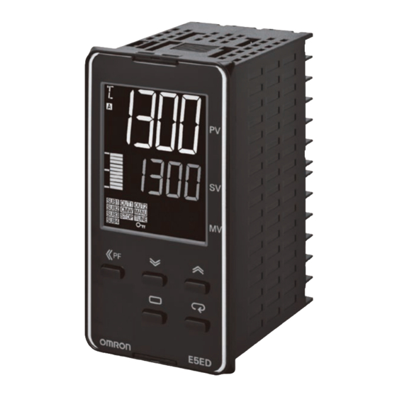
- Page 14 E5CD-800/E5CD-B-800 Nomenclature E5CD-800/E5CD-B-800 Front panel Temperature unit Operation indicators No. 1 display PV or specified parameter Top View No. 2 display SP or specified parameter value Bar display Use the U D Keys to set the parameter. Press O Key once to go to Adjustment Level.
- Page 15 E5CD-800/E5CD-B-800 Accessories (Order Separately) Terminal Covers (Cannot be used on a Push-In Plus terminal block type) E53-COV17 48.8 Terminal Covers (Cannot be used on a Push-In Plus terminal block type) E53-COV23 (Three Covers provided.) Terminal Cover (E53-COV23) 44.8 Waterproof Packing The Waterproof Packing is provided with the Digital Temperature Controller.
-
Page 16: Current Transformers
E5CD-800/E5CD-B-800 Current Transformers E54-CT1 Thru-current (Io) vs. Output Voltage (Eo) (Reference Values) Filler E54-CT1 or E54-CT1L 5.8 dia. (epoxy) Maximum continuous heater current: 50 A (50/60 Hz) Case ± Number of windings: ± Ω Winding resistance: 10.5 100V Frequency: 50 Hz ∞... -
Page 17: Connection Example
Filler 12 dia. (epoxy) E54-CT3 or E54-CT3L Case Maximum continuous heater current: 120 A (50/60 Hz) (PBT) (Maximum continuous heater current for an OMRON Digital Temperature Controller is 50 A.) 40 × 40 Number of windings: 400±2 Ω Winding resistance: 8±0.8... -
Page 18: Mounting Example
E5CD-800/E5CD-B-800 Adapter Y92F-45 Note: 1. Use this Adapter when the Front Panel has already been prepared for the E5B@. 2. Only black is available. 3. You cannot use it together with the Y92F-49 Adapter that is enclosed with the Controller. Fixture (Accessory) 69.6 to 77.6 72 ×... -
Page 19: Mounting Adapter
E5CD-800/E5CD-B-800 Waterproof Cover Mounting Adapter Y92F-49 Y92A-48N 21.9 The Mounting Adapter is provided with the Digital Temperature Controller. Order this Adapter separately if it becomes lost or damaged. 87.7 79.2 67.6 28.9 Front Cover Front Cover Y92A-48D Y92A-48H Note: This Front Cover cannot be used if the Waterproof Packing is This Front Cover is hard type. -
Page 20: Filter Adjustment)
For the most recent information on models that have been Output ON/OFF Count). certified for safety standards, refer to your OMRON website. • Basic performance is same as the E5C-800 standard models. • Draw-out structure for easy maintenance (Screw terminal Refer to Safety Precautions on 43. -
Page 21: Model Number Legend
E5ED-800/E5ED-B-800 Model Number Legend and Standard Models Model Number Legend Models with Screw Terminal Blocks E5ED-@@ 2 @ D M -@@@ (Example: E5ED-RX2ADM-800) −− − − − − −−− B C D E No. of Power Model Meaning Control outputs Terminal Input auxiliary... - Page 22 E5ED-800/E5ED-B-800 Model Number Legend Models with Push-In Plus Terminal Blocks E5ED-@@ 2 @ B M -@@@ (Example: E5ED-RX2ABM-800) −− − − − − −−− B C D E No. of Power Model Meaning Control outputs Terminal Input auxiliary supply Options 1 and 2 type type...
- Page 23 E5ED-800/E5ED-B-800 Optional Products (Order Separately) Terminal Covers Current Transformers (CTs) (Cannot be used on a Push-In Plus terminal block type) Hole diameter Model Model 5.8 mm E54-CT1 E53-COV24 (3pcs) 5.8 mm E54-CT1L* 12.0 mm E54-CT3 Waterproof Packing 12.0 mm E54-CT3L* Model *Lead wires are included with these CTs.
- Page 24 E5ED-800/E5ED-B-800 Specifications Ratings A in model number: 100 to 240 VAC, 50/60 Hz Power supply voltage D in model number: 24 VAC, 50/60 Hz; 24 VDC Operating voltage range 85% to 110% of rated supply voltage Models with option selection of 800: 6.6 VA max. at 100 to 240 VAC, and 4.1 VA max. at 24 VAC or Power consumption 2.3 W max.
- Page 25 E5ED-800/E5ED-B-800 Input Ranges Thermocouple/Platinum Resistance Thermometer (Universal inputs) Sensor Platinum resistance Infrared temperature Thermocouple type thermometer sensor Sensor 10 to 60 to 115 to 140 to Pt100 JPt100 PLII 70°C 120°C 165°C 260°C specification 2300 2300 1800 1800 1700 1700 1700 1600 1500...
- Page 26 E5ED-800/E5ED-B-800 Alarm Types Each alarm can be independently set to one of the following 17 alarm types. The default is 2: Upper limit. (see note.) Auxiliary outputs are allocated for alarms. ON delays and OFF delays (0 to 999 s) can also be specified. Note: In the default settings for models with HB or HS alarms, alarm 1 is set to a heater alarm (HA) and the Alarm Type 1 parameter is not displayed.
- Page 27 E5ED-800/E5ED-B-800 *1. With set values 1, 4 and 5, the upper and lower limit values can *4. Set value: 5, Upper- and lower-limit with standby sequence be set independently for each alarm type, and are expressed as For Upper- and Lower-Limit Alarm Described Above *2 “L”...
- Page 28 E5ED-800/E5ED-B-800 Characteristics Thermocouple: (±0.3% of indication value or ±1°C, whichever is greater) ±1 digit max. *1 Platinum resistance thermometer: Indication accuracy (±0.2% of indication value or ±0.8°C, whichever is greater) ±1 digit max. (at the ambient temperature of 23°C) Analog input: ±0.2% FS ±1 digit max.
- Page 29 Number of connected Digital Temperature Controllers: Programless 32 max. (Up to 16 for the FX3) communications Applicable PLCs OMRON PLCs CS Series, CJ Series, CP Series, NJ Series, or NX1P Mitsubishi Electric PLCs MELSEC Q Series, L Series, FX3 Series, or iQ-R Series...
- Page 30 E5ED-800/E5ED-B-800 External Connections E5ED-800 E5ED-@@ 2 @ D M - @ @ @ Control output 1 Auxiliary outputs 1, 2 (1) (2) (3) (4) (5) Relay output Relay output ↑ Terminal type 250 VAC, 5 A 250 VAC, 2 A (resistive load) (resistive load) Voltage output...
- Page 31 E5ED-800/E5ED-B-800 E5ED-B-800 (Push-In Plus Terminal Blocks) E5ED-@@ 2 @ B M - @ @ @ Control output 1 Control output 2 Auxiliary outputs 1, 2, 3, 4 Relay output Relay output Relay output (1) (2) (3) (4) (5) 250 VAC, 5 A Models with 4 auxiliary outputs 250 VAC, 5 A (resistive load) ↑...
- Page 32 E5ED-800/E5ED-B-800 Isolation/Insulation Block Diagrams Sensor input and CT input Communications and event inputs Voltage output (for driving SSR) and linear current output Power supply Relay output Auxiliary outputs 1 Auxiliary outputs 2 : Reinforced insulation : Functional isolation Nomenclature E5ED-800/E5ED-B-800 Front panel Top View No.
- Page 33 E5ED-800/E5ED-B-800 Dimensions (Unit: mm) Controllers E5ED-800 (64) Waterproof Packing Mounting Adapter (Accessory, Y92S-P9 (Accessory, Y92F-51 (also available for (also available for ordering separately)) ordering separately)) E5ED-B-800 (71.4) 67.4 Waterproof Packing Mounting Adapter (Accessory, Y92S-P9 (Accessory, Y92F-51 (also available for (also available for ordering separately)) ordering separately)) * Selections for Control Outputs 1 and 2: QR or RR...
- Page 34 E5ED-800/E5ED-B-800 Accessories (Order Separately) Terminal Covers (Cannot be used on a Push-In Plus terminal block type) E53-COV24 (Three Covers provided.) Waterproof Packing Y92S-P9 (for DIN 48 × 96) The Waterproof Packing is provided with the Digital Temperature Controller. Order the Waterproof Packing separately if it becomes lost or damaged. The Waterproof Packing can be used to achieve an IP66 degree of protection.
- Page 35 E5ED-800/E5ED-B-800 Waterproof Cover Y92A-49N (for DIN 48 × 96) 21.9 131.7 67.6 28.9 Draw-out Jig (Cannot be used on a Push-In Plus terminal block type) Y92F-59 Use this Draw-out Jig to remove the interior body of the Digital Temperature Controller from the case to perform maintenance without removing the terminal wiring.
- Page 36 E5ED-800/E5ED-B-800 Current Transformers E54-CT1 Thru-current (Io) vs. Output Voltage (Eo) (Reference Values) Filler E54-CT1 or E54-CT1L 5.8 dia. (epoxy) Maximum continuous heater current: 50 A (50/60 Hz) Case ± Number of windings: ± Ω Winding resistance: 10.5 100V Frequency: 50 Hz ∞...
- Page 37 Filler 12 dia. (epoxy) E54-CT3 or E54-CT3L Case (PBT) Maximum continuous heater current: 120 A (50/60 Hz) (Maximum continuous heater current for an OMRON Digital Temperature Controller is 50 A.) 40 × 40 Number of windings: 400±2 Ω Winding resistance: 8±0.8...
- Page 38 MEMO...
-
Page 39: Operation
E5@D-800 Operation Setting Levels Diagram This diagram shows all of the setting levels. To move to the advanced function setting level and calibration level, you must enter passwords. Some parameters are not displayed depending on the protect level setting and the conditions of use. Control stops when you move from the operation level to the initial setting level. - Page 40 E5@D-800 Operation Parameter Flow This section describes the parameters set in each level. Pressing the M (Mode) Key at the last parameter in each level returns to the top parameter in that level. Hold down the M Key to move through the parameters in reverse. Some parameters may not be displayed depending on the model and other settings.
-
Page 41: Monitor/Setting Item Level
E5@D-800 Monitor/Setting Item Level Monitor/Setting Monitor/Setting Monitor/Setting Monitor/Setting Monitor/Setting Item Display 1 Item Display 4 Item Display 5 Item Display 3 Item Display 2 Note: The monitor/setting items to be displayed is set in the Monitor/Setting Item 1 to 5 parameters (advanced function setting level). Press the O Key for at least 1 s. - Page 42 E5@D-800 Error Displays (Troubleshooting) When an error occurs, the No. 1 display or No. 2 display shows the error code. Take necessary measure according to the error code, referring the following table. Display Name Meaning Action Operation The input value exceeded the control Check the wiring for input to be sure After the error occurs and it is range.*...
-
Page 43: Safety Precautions
E5@D-800 Safety Precautions Be sure to read the precautions for all E5CD-800/E5ED-800 models in the website at: http://www.ia.omron.com/. Warning Indications If the output relays are used past their life expectancy, Indicates a potentially hazardous contact fusing or burning may occasionally occur. -
Page 44: Recommended Wires
E5@D-800 9. Make sure that the rated voltage is attained within 2 seconds of Precautions for Safe Use turning ON the power using a switch or relay contact. If the voltage is applied gradually, the power may not be reset or output Be sure to observe the following precautions to prevent operation malfunctions may occur. - Page 45 E5@D-800 25.Observe the following precautions when you wire the E5D-B. Precautions for Correct Use • Always follow the E5 D Digital Temperature Controllers User's Manual (Cat. No. H224). Service Life • Do not wire anything to the release holes. 1.
-
Page 46: Precautions During Operation
E5@D-800 Precautions during Operation Mounting to the Panel (E5ED-800/E5ED-B-800) 1. For waterproof mounting, waterproof packing must be installed on 1. It takes approximately two seconds for the outputs to turn ON from the Digital Temperature Controller. Waterproofing is not possible after the power supply is turned ON. - Page 47 E5@D-800 Removing the draw-out jig when only one hook is caught 3. Pull out the Draw-out Jig together with the front panel. Do not pull with excessive force. Slowly pull out the Digital Temperature in the draw-out jig insertion hole Controller laterally.
-
Page 48: Precautions When Wiring
E5@D-800 Precautions when Wiring Connecting Stranded Wires Use the following procedure to connect the wires to the terminal block. • Separate input leads and power lines in order to prevent external 1. Hold a flat-blade screwdriver at an angle and insert it into the noise. - Page 49 10 AI 0,75-8 H0.75/14 216-202 0.75 SDI 0.4✕2.5✕75 Weidmuller 12 AI 0,75-10 H0.75/16 216-242 * OMRON's exclusive purchase model XW4Z-00B is available to 10 AI 1-8 H1.0/14 216-203 1/1.25 18/17 order as SZF 0-0,4✕2,5 (manufactured by Phoenix Contact). 12 AI 1-10 H1.0/16...
- Page 50 Temperature Sensors for Packaging Machines Accurately Measure Seal Temperature. Temperature Sensors for Packaging Machines. • Heat resistance (sleeve: 0 to 260°C) and direct installation to heat bars. • Greater flexibility in the movable section (models with 30 cores). • Protective tubing diameter of 1 mm with ground for high- speed response.
- Page 51 Special models for Packaging Machines Model Number Legend The type of protective tubing length, and lead length can be specified as shown below. E 5 2 - C A D = 1 Code Element type Protective tubing length L (cm) Specify the length in centimeters within the following range: Unit (cm) Diameter (D)
-
Page 52: List Of Models
Dimensions Y-type crimp terminals for M3.0 Y-type crimp terminals for M3.0 Red: + Sleeve (PPS resin) *2 Product label Mark tube (white) Sheath (ASTM316L) *3 Shrinkable tube (blue) +0.1 S1: 5.5 dia. −0.3 Lead wire *1 1 ±0.05 dia. +0.1 S1: 2.8 dia. -
Page 53: Installation Method
Installation Method A Temperature Sensor for Packing Machines has a diameter of 1.0 mm. To measure the temperature close to the seal surface, mount the Sensor as close as possible to the surface. The following installation methods are assumed. Example 1: Groove for Temperature Sensor created in heating plate and Temperature Sensor secured with mounting brackets. - Page 54 MEMO...
-
Page 55: Terms And Conditions Agreement
Data presented in Omron Company websites, catalogs and other materials is provided as a guide for the user in determining suitability and does not constitute a warranty. It may represent the result of Omron’s test conditions, and the user must correlate it to actual application requirements. - Page 56 The Netherlands Hoffman Estates, IL 60169 U.S.A. Tel: (31)2356-81-300/Fax: (31)2356-81-388 Tel: (1) 847-843-7900/Fax: (1) 847-843-7787 © OMRON Corporation 2017-2021 All Rights Reserved. OMRON (CHINA) CO., LTD. OMRON ASIA PACIFIC PTE. LTD. In the interest of product improvement, Room 2211, Bank of China Tower, No.
Need help?
Do you have a question about the E5CD-B-800 Series and is the answer not in the manual?
Questions and answers