Table of Contents
Advertisement
Quick Links
Advertisement
Table of Contents

Related Manuals for ZKTeco PS-55B Series


Summary of Contents for ZKTeco PS-55B Series
- Page 1 USER MANUAL Network Speed Dome Version: 1.0 Date: June 2018 Contents...
- Page 3 WARNINGS AND CAUTIONS WARNING TO REDUCE THE RISK OF FIRE OR ELECTRIC SHOCK, DO NOT EXPOSE THIS PRODUCT TO RAIN OR MOISTURE. DO NOT INSERT ANY METALLIC OBJECTS THROUGH VENTILATION GRILLS OR OPENINGS ON THE EQUIPMENT. CAUTION EXPLANATION OF GRAPHICAL SYMBOLS The lighting flash with arrowhead symbol, within an equilateral triangle, is intended to alert the user the presence of non-insulated “dangerous voltage”...
- Page 4 PRECAUTIONS: Persons without technical qualifications should not attempt to operate this dome device before reading this manual thoroughly. Remove any power to the dome before attempting any operations or adjustments inside the dome cover to avoid potential damage to the mechanism. Inside the dome cover there are precision optical and electrical devices.
- Page 5 IMPORTANT SAFEGUARDS 1. Read these instructions before attempting installation or operation of dome device. 2. Keep these instructions for future reference. 3. Heed all warnings and adhere to electrical specifications follow all instructions. 4. Clean only with non abrasive dry cotton cloth, lint free and approved acrylic cleaners. 5.
-
Page 7: Table Of Contents
INDEX WARNINGS AND CAUTIONS ..............................1 WARNING ................................... 1 CAUTION .................................... 1 EXPLANATION OF GRAPHICAL SYMBOLS ......................1 PRECAUTIONS: ................................. 2 IMPORTANT SAFEGUARDS ............................3 1 Product Introduction ................................1 1.1 Package Contents ..............................1 1.2 Specification ................................2 1.3 Performance Features ............................4 2 Installation .................................... - Page 8 2.6 Setting ..................................20 2.6.1 System ..............................20 2.6.2 Network .............................. 23 2.6.3 Management Software ......................... 28 2.6.4 IP Cameras ............................28 2.6.5 Audio & Video ..........................33 2.6.6 PTZ Function............................. 37 2.6.7 Alarm ..............................39 2.6.8 User ..............................40 2.6.9 log .................................
-
Page 9: Warnings And Cautions
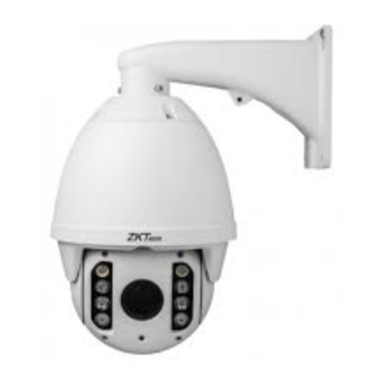
1 Product Introduction 1.1 Package Contents IP IR Speed dome Wall mount bracket Power supply Screws kits User manual CD ( with CMS etc.) 1 Product Introduction... -
Page 10: Precautions
1.2 Specification Image Sensor 1/3’’ SONY CMOS Preview video resolution 1920×1080 Mini Illumination Color:0.5Lux B/W:0.05Lux IR ON:0Lux Signal Noise Ratio ≥50dB Focus Auto/Manual IR-Cut F-Stop F1.6(color),F1.8(IR on),Auto Close-up INF(Color),1000mm(Far ) Horizontal Rotation Range & Speed Range:360° ,Speed:0.02~480°/s Tilt Rotation Range & Speed Range:93°... -
Page 11: Important Safeguards
60Hz:30fps(1920×1080/432×240) Frame rate 60Hz:30fps(1280×720/432×240) Compressed Image Format H.264/MPEG-4 TCP/IP,HTTP,NTP,IGMP,DHCP,UDP,SMTP,RTP,RTSP,ARP,DDNS,D Communication Protocol NS,HTTPS,P2P Compressed Image Rate 500Kbps~7Mbps Power DC 12V-4A Back End Record Mode PDVR, PC, Megapixel HD system card, NVR, IP-SAN Power Consumption ≤ 25W Operating Temperature Indoor: 0°~ +40° Outdoor: -40°~ +60°... -
Page 12: Performance Features
1.3 Performance Features Use high performance 1/3” CMOS, great low light performance. Support high definition resolution 1280x720P / 1920×1080P. 10x / 18x / 30x / 36x zoom as optional. IR distance reach up to 50m (10x)-180m (20x-36x). Dual-stream output. -
Page 13: Installation
2 Installation 2.1 Dimension Ceiling Installation Bracket Installation 2 Installation... -
Page 14: Installation
2.2 Installation 2.2.1 Wall Mounted Installation conditions: Wall mounted dome can be used in the hard wall structure whose thickness should be enough to install expansion bolt in indoor and outdoor environment. The wall can bear at least 4 times the weight of the dome. -
Page 15: Corner Mounted
b. As shown in fig 2.4, fix the wall hanging bracket on the wall with wire and cable through it. Fig 2.4 2.2.2 Corner Mounted Installation conditions: Corner mounted dome can be used in the hard wall structure with an angle of 90° whose thickness should be enough to install expansion bolt in indoor and outdoor environment. - Page 16 b. As shown in fig 2.6, use M8 screw nut to fix the base of corner mounted on the wall with all cables through the center holes of the corner mounted, marine glue and bracket. Enough wiring length should be left. Fig 2.6 c.
-
Page 17: Pole Mounted
2.2.3 Pole Mounted Installation conditions: Pole mounted dome can be used in the hard pole structure in indoor and outdoor environment whose diameter should match the installation size of stainless hose clamps. Factory default is 6 inches stainless hose clamps (fit φ130-152mm pillar). The pole structure can bear at least 4 times the weight of the dome. Install corner mounted attachment and wall hanging bracket: a. -
Page 18: Ceiling Mounted
2.2.4 Ceiling Mounted Installation conditions: Ceiling mounted dome with thick pole can be used in the hard ceiling structure whose thickness should be enough to install expansion bolt in indoor and outdoor environment. The ceiling can bear at least 4 times the weight of the dome. - Page 19 Note: If the dome is used in the outdoor conditions, use the silica gel on the faying surface of the base of hang ceiling and the ceiling board and around the out-holes to be sure water proof c. As shown in the fig 2.12, tighten the boom with electrical wire and cable through it on the base of ceiling and screw up the M4 screw.
-
Page 20: Connection
2.3 Connection 2.3.1 PTZ Connection Way Before connecting, please turn off the power and read carefully the instructions of all connected devices. 2.3.2 Connecting the Device The device can be directly connected to the computer and the network; Please use the cross-over cable when connecting to the computer; Please use the straight through cable when connecting to the network. -
Page 21: Install Video Software
Fig 2.13 3. Choose internet icon, click “Customs level”. Then the follow pops up: Fig 2.14 4. Change option “Download unsigned ActiveX controls” into “Enable” or “Prompt”. User can optionally change “Running ActiveX controls and plug-in” into “Start” to avoid the prompt of running. - Page 22 (2) Install and run controls Please click “Run” in the prompt box above, and the controls are to be installed to run. After that, you are able to view the video in real time. Note: 1. The steps above are not sequential. After operating (1) and (2), if not successful, then please try the website downloading method.
-
Page 23: Login Ie Interface
2.4 Login IE Interface When the system starts up for 110 seconds, please open the IE browser, input the IP camera address. The default IP is http://192.168.1.110 (Note: System default subnet mask is 255.255.255.0; default gateway is 192.168.1.110. Please correctly set the local IP address before login and access. ) The language for login interface is consistent with the operation system. - Page 24 Fig 2.16 The IP Camera supports H.264/MJPEG dual encoding format. After login, you will enter the real time video interface in the format of H.264 compression. User can click “MJPEG” button, and enter the real time video in the format of MJPEG . Please refer to picture as following: Fig 2.17 2.4 Inch TFT POE Terminal User Manual...
-
Page 25: Browser
2.5 Browser In the browsing interface, you can set video browse, PTZ control, commonly used shortcuts (like photography, recording, audio input, audio output, Language setting, etc.) to get the satisfying video. 2.5.1 Video Browsing Video Browsing: For camera capture display setting, you can set the video type, video size, play mode, image color and illumination. -
Page 26: Ptz Function
Fig 2.19 PTZ direction: adjust the PTZ’s eight directions. Horizontal speed: 1 — 8 optional Vertical speed: 1 — 8 optional 2.5.3 PTZ Function PTZ functions: preset, auto pan, pattern, tour. (Patternis not available) Fig 2.20 2.4 Inch TFT POE Terminal User Manual... -
Page 27: Common Shortcuts
2.5.4 Common Shortcuts Common shortcuts: 3D location photograph, record, audio input, audio output, Languages selection Fig 2.21 Frequently set common functions of the IP cameras. The storage path of photographing and recording complies with the one from setting .The snapshots are stored in the name of IP address and time of the device. -
Page 28: Setting
2.6 Setting Setting: detailed setting of system, network, IPC, audio & video, PTZ functions, alarm, user, Blog. Fig 2.22 2.6.1 System System: upgrade the system info, time and maintenance. System info: The initial interface of system setting is the display interface of system info. User can learn more about the setting info, like basic info, network parameter alarm setting, NTP setting, H.264 video parameter setting, MJPEG video parameter setting. - Page 29 Fig 2.23 Basic Info: The IPC’s version number, time zone, product series, serial number. Network parameter: MAC address, IP address, default gateway, subnet mask. Alarm setting: Alarm server IP, alarm correlation. NTP setting: NTP server IP. H.264 video parameter: main stream/sub stream resolution, frame rate, bit rate, I/P rate. MJPEG parameter setting: resolution, frame rate.
- Page 30 time zones are optional for setting, range “GMT-12:00~GMT~GMT+13:00”. Of all, GMT+08:00 is China Beijing time. The default setting is GMT standard time. If your local time is daylight saving time, please click “automatically adjust clock for daylight saving changes” option. NTP setting: set NTP server IP is the same with the device’s IP address.
-
Page 31: Network
First, user can remotely submit system upgrade request via internet. According to user’s submission, we’ll send the device’s relative edition upgrade for confirmation, and provide the latest software downloading, helping upgrade the IP Camera. User can upgrade the system as the following steps: Click “Browsing”... - Page 32 Network: setting of the device’s network parameter. Fig 2.27 DHCP: Dynamic Host Configuration Protocol, one of TCP/IP, mainly allocating dynamic IP address for network clients. Select “on”, the camera’s IP address and the subnet mask cannot be modified, but automatically allocated by the host. Select “off”, you’re supposed to set the network data by yourself and make sure the IP address and gateway address on the same segment.
- Page 33 SMTP: SMTP belongs to TCP/IP, help to find the next destination for each computer when sending or transiting letters . Fig 2.29 Server IP: set up mail server IP. Sender: set up the email address of the sender. Authentication: Turn on or off the authentication function via mail server verification.
- Page 34 QoS: Quality of Service, a kind of network secure mechanism, a technology of solving network delay and congestion. Fig 2.31 IGMP: It is a multi-cast protocol of internet family, helping IP Host report their membership to the adjacent routers. Fig 2.32 Fig 2.33 DDNS: The user’s dynamic IP address is mapped to a fixed domain name resolution service.
- Page 35 Fig 2.34 PORT: an interface, passing data between the computer and other devices (e.g. Printer, mouse, keyboard, monitors), among network, or other computers in connection. Fig 2.35 Cloudlens Fig 2.36 2 Installation...
-
Page 36: Management Software
2.6.3 Management Software This section is very simple, and here is the introduction: Software initial user name is admin, while password is 123456. After login, you can find “search” button on the top of the interface, and click to search all IP cameras in the LAN area. - Page 37 Basic set: Enable and disable setting of camera system, noise, mirror, BLC and other function (this depends on the function of zoom module). Fig 2.38 Power Frequency: 50HZ domestic use; 60HZ abroad use. Horizon Mirror: image horizontal mirror display. Vertical Mirror: image vertical mirror display. BLC: divided into different zones and each zone expose separately.
- Page 38 Expose settings: expose mode, Color to Black, Scene select, and AGC setting. Fig 2.39 Expose set: program mode, for normal video mode; shutter mode, for fast moving objects. Scene Select: Indoor, eliminate indoor lighting flash; Outdoor, eliminate outdoor overexposure. Slow shutter: shutter setting, default is off. AGC: A kind of control method of automatically adjusting amplifier circuit with signal intensity.
- Page 39 Effect Setting: setting of image sharpness, brightness, contrast, saturation. Fig 2.40 Brightness: unit projected area of brightness intensity would bring the overall brightness of the image. Over higher brightness would cause the insufficient permeability. Sharpness: also called “resolution”, which reflects the image plane clarity and edge sharpness. Adjust the sharpness higher, the contrast details on the plane image become higher and then the image looks much clear.
- Page 40 saturation is. 3D Noise: Noise reduction adjust during night White Balance: Balance the white. Regardless of any light, the white objects would return to white color. Fig 2.41 White Balance: auto, cloudy, Day (D65), Day (50), Fluorescent Light, Filament Lamp, Sun Up, Manual. Reset: fix the camera data.
-
Page 41: Audio & Video
2.6.5 Audio & Video Audio & Video: setting of camera audio, video, OSD, and path. Fig 2.43 Video: Main Stream, Minor Stream, MJPEG. Resolution: 1920*1080, 1280*1024, 1280*960, 1280*720, 640*480. Frame: the number of IP Cam’s processing compressed frames. If the number of the frame isset bigger, the image would become more continuity, but it reduces the performance of CPU processing other events. - Page 42 Bit rate: 512K, 1024K, 2048K, 3072K, 4096K, 5120K, 6144K. The bit rate is higher, the footprint is bigger, while the image is better. 720P/2M 1080P/4M are commonly used. I/P rate: the contrast of I frame and P frame. The bigger the ratio is, the data is smaller. Recommendation: set 15. Text Overlay: Text, time, date can be displayed on the screen.
- Page 43 Time OSD: set the position of time display, ON or OFF of the time display. Motion Detection: commonly used in unmanned video and alarm. Fig 2.45 【Sensitivity】: Setting motion detection sensitivity. The sensitivity can be set from 1 to 100. The smaller the number is, the higher the sensitivity is.
- Page 44 Privacy Zone: setting the privacy zone of the camera. This zone can not move . It is available if PTZ is in a fixed place. Fig 2.46 IP Cameras support privacy zone function. When a special zone is not allowed to be seen by the operator, you can use this function.
-
Page 45: Ptz Function
Path: storage path of IE recording and snapshot. Fig 2.47 The default is C drive control folder. Click browse to re-select the storage path. For the type of the file, photos is jpg/bmp and video is avi/ifv. 2.6.6 PTZ Function PTZ function: preset, auto tour , PTZ protocol. - Page 46 Fig 2.48 Auto Tour: Fig 2.49 2.4 Inch TFT POE Terminal User Manual...
-
Page 47: Alarm
Protocol set: Fig 2.50 2.6.7 Alarm Alarm: grounded circuit and open circuit for I/O. Set net contact or local contact. 2 Installation... -
Page 48: User
Fig 2.51 The IP camera supports 2 channel alarm in. User can set grounded or open circuit for each I/O. Alarm out contact: transmission method of alarm signal. Local contact: local alarm out. Default local contact. Net contact: internet transmission. Note: The function requires the synchronous use of digital video management software, e.g. -
Page 49: Log
Add user: click the image “ ”, you will get thefollowing dialog: Fig 2.53 Input user name and password. Fig 2.54 2.6.9 log Log: recording of each operation Fig 2.55 2 Installation... -
Page 50: Function Instruction
3. Function Instruction 3.1 Basic Function Dome Running Control joystick or up, down, left and right key in the keyboard. Zoom Press ZOOM- button to make the lens farther and minify the scene. Press ZOOM+ button to make the lens closer and magnify the scene. Focus ... -
Page 51: Special Function
3.2 Special Function The follow presets are predefined as special function, please shot+ preset No+ enter to enable those functions: PREST FUNCTION PRESET FUNCTION Reset Turn on far light Run Wiper Turn on near light Stop Wiper 91(31) Call A-B scan Pattern 1 Set left point of A-B scan Pattern 2... -
Page 52: Appendix I Anti-Lightning, Anti-Surge
Appendix I Anti-lightning, Anti-surge This product is extremely air discharge and lightning protection with TVS tube technology, which can effectively prevent the transient lightning below voltage 3000V, surge and damages caused by other types of pulse signals. However, necessary protective measures should be made in the premise of ensuring electrical safety for outdoor installation according to the actual situation: ·Signal transmission line must be at least 50 meters far away from the high-voltage equipment or ... -
Page 53: Appendix Ii Clean Transparent Cover
Appendix II Clean Transparent Cover In order to assure a clear image of dome, the under cover of dome should be cleaned regularly. Be careful when cleaning and hold the outer ring of under cover by hands to avoid directly touching ... -
Page 54: Appendix Iii Exception Handling
Appendix III Exception Handling Issue Possible Reason Solution Verify that the orientation of the Cable harness is improperly connected connector input After power is Input power voltage is too low Verify the voltage of the input power applied, there is no action (self-test) Power supply does not work Change a new power supply... -
Page 55: Copyright Statement
Copyright Statement This copyright is merely belong to the manufacturer. Without permission, please don’t plagiarize or copy the contents of this book in any form or by any means. The company follows the policy of continuous development. Therefore, the company reserves the right to modify or improve the products described in this manual without notice.
Need help?
Do you have a question about the PS-55B Series and is the answer not in the manual?
Questions and answers