Table of Contents
Advertisement
Quick Links
RL78/G1N Fast Prototyping
Board
16
16
16-Bit Single-Chip Microcontrollers
RL78 Family
All information contained in these materials, including products and product specifications, represents
information on the product at the time of publication and is subject to change by Renesas Electronics
Corporation. without notice. Please review the latest information published by Renesas Electronics
Corporation. through various means, including the Renesas Electronics Corp. website
(http://www.renesas.com).
www.renesas.com
User's Manual
Rev.1.00 Jun 2020
Advertisement
Table of Contents

Subscribe to Our Youtube Channel
Related Manuals for Renesas RL78/G1N


Summary of Contents for Renesas RL78/G1N
- Page 1 All information contained in these materials, including products and product specifications, represents information on the product at the time of publication and is subject to change by Renesas Electronics Corporation. without notice. Please review the latest information published by Renesas Electronics Corporation.
- Page 2 Renesas Electronics disclaims any and all liability for any damages or losses incurred by you or any third parties arising from the use of any Renesas Electronics product that is inconsistent with any Renesas Electronics data sheet, user’s manual or other Renesas Electronics document.
- Page 3 Unit Products The following usage notes are applicable to all Microprocessing unit and Microcontroller unit products from Renesas. For detailed usage notes on the products covered by this document, refer to the relevant sections of the document as well as any technical updates that have been issued for the products.
- Page 4 This manual is designed to provide the user with an understanding of the basic specifications and correct usage of this product. The target users are those who are using this product to evaluate the RL78/G1N microcontroller and debug programs. The readers of this manual must have basic knowledge about the features of microcontrollers and debuggers.
- Page 5 Micro-controller Unit n/a (NA) Not applicable n/c (NC) Not connected Personal Computer Random Access Memory Renesas Flash Programmer Read Only Memory Serial Peripheral Interface Universal Serial Bus UART Universal Asynchronous Receiver/Transmitter Watchdog timer All trademarks and registered trademarks are the property of their respective owners.
-
Page 6: Table Of Contents
6. Handling Precautions ....................... 14 Power to be Supplied ..........................14 Remodeling the Board ..........................14 Limitation on the Number of Connected RL78/G1N Fast Prototyping Boards ........14 Power-Supply Circuits and Usage Conditions ..................14 7. Developing Code ......................16 Using the e studio ........................... -
Page 7: Overview
Quick Start Guide • Purpose This product is an evaluation tool for a Renesas MCU. This user’s manual describes the hardware specifications, the method of setting the switches on the board, and the basic procedures for setting this product up. -
Page 8: Rl78/G1N Fast Prototyping Board: Table Of Specifications
Emulator reset headers* Headers: 2 pins x 2 Notes: 1. The intended power supply for the RL78/G1N on the board as shipped is VBUS (5 V). For details, refer to Chapter 5, User Circuits. 2. This part is not mounted. -
Page 9: Block Diagram
RL78/G1N Fast Prototyping Board 1. Overview Block Diagram Figure 1-1 shows the block diagram of this product. Arduino Nano connectors connector multiplexed with the MCU headers Evaluation MCU Emulator circuit (RL78/G1N) Emulator reset Power Reset switch headers User LED (EJ1 and EJ2) -
Page 10: Board Layout
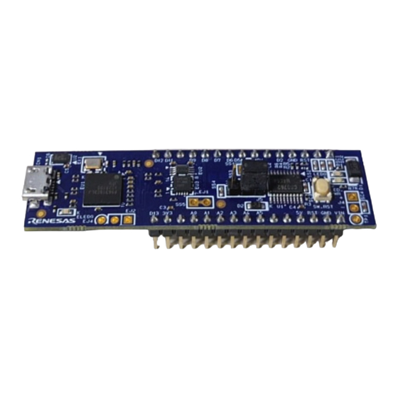
RL78/G1N Fast Prototyping Board 2. Board Layout 2. Board Layout Figure 2-1 shows the external appearance of the top side of this product. Interface compatible with Arduino Nano User LED (MCU pin header J1) Power-supply Reset switch selection header Micro-USB... -
Page 11: Parts Layout
RL78/G1N Fast Prototyping Board 3. Parts Layout 3. Parts Layout Figure 3-1 shows the parts layout of this product. 67.00 D12 D11 D10 D9 D8 D7 D2 GND RST D0 <-J1 CP1_1 ER17 CP2_1 CP2_2 ER16 ER18 LED0 ER14 ER12... -
Page 12: Operating Environment
RL78/G1N Fast Prototyping Board 4. Operating Environment 4. Operating Environment Figure 4-1 shows the operating environment of this product. Install the IDE from the following URL on the host PC. The installer automatically installs all required drivers along with the IDE. -
Page 13: User Circuits
USB Connector The connector shape is micro-USB Type-B for the IDE and for the Renesas Flash Programmer (RFP). Connect the USB connector to the computer by a USB cable. If the power supply on the host side is on, the power is supplied to this product at the same time as connection of the cable. -
Page 14: Arduino Nano Connectors Multiplexed With The Mcu Headers
RL78/G1N Fast Prototyping Board 5. User Circuits Arduino Nano Connectors Multiplexed with the MCU Headers The specification of the Arduino Nano connector is on the assumption that Arduino Nano shields are to be connectable. However, we do not guarantee connection to all types of Arduino Nano shield. - Page 15 RL78/G1N Fast Prototyping Board 5. User Circuits Table 5-1 Pin Assignments of the Arduino Nano Connector Part No. in Name of Arduino RL78/G1N the Circuit Nano Signal Power Port Analog Serial Others Schematics Supply J1-1 PD1/TXD (11) (P06/TXD)* (TXD0)* ...
-
Page 16: Clock
The emulator is placed in the forced reset state by short-circuiting the emulator reset header (EJ2). At this time, remove SS5 and make EJ1 open-circuit. This allows stand-alone operation of the RL78/G1N independently of control by the IDE while the IDE is applying a forcible reset. Figure 5-2 shows the position of the emulator reset headers (EJ2, EJ1, and SS5) (only through-holes are provided;... -
Page 17: Power-Supply Selection Header
Power-Supply Selection Header The operating voltage of the RL78/G1N can be changed to VBUS (5 V) or 3.3 V with the use of this header (J5). Figure 5-3 shows the connection of the header for VBUS (5-V) output, and Figure 5-4 shows the connection of the header for 3.3-V output. -
Page 18: External Power-Supply Header
5.11 External Power-Supply Header When operating the RL78/G1N at a desired external input voltage, or when more current is required than the USB is capable of supplying, use the external power-supply header (J4) to supply power. The usable voltage range is from 2.25 V to 5.5 V. -
Page 19: Current Measurement Header
RL78/G1N Fast Prototyping Board 5. User Circuits 5.12 Current Measurement Header The current measurement header (J3) is used to measure the current drawn by the evaluation MCU (the J3 header component is not mounted). The current drawn can be measured by connecting an ammeter to the evaluation MCU. -
Page 20: Handling Precautions
5.5 V)* Notes: 1. Connecting the RL78/G1N Fast Prototyping Board to a board supported by an Arduino Nano shield shall be conducted at the user’s own responsibility and should only proceed after confirming the specifications of the power supply and interfaces. - Page 21 RL78/G1N Fast Prototyping Board 6. Handling Precautions 5 V (VBUS) Arduino 5 V 3.3 V Arduino 3.3 V (VBUS) 5 V (VBUS) RL78/G1N 3.3 V 3.3 V USB Micro B Regulator VBUS (Not mounted) Power-supply Current selection header measurement (J5)
-
Page 22: Developing Code
[Power Target From The Emulator]: Select [No]. • [Target Device]: Select [R5F11Y68]. • R5F11Y68 Figure 7-1 Settings of the e studio Note: Do not connect another RL78/G1N Fast Prototyping Board to your PC while this product is already connected. R20UT4810EJ0100 Rev.1.00 Page 16 of 27 Jun.16.20... -
Page 23: Using Cs
RL78/G1N Fast Prototyping Board 7. Developing Code Using CS+ Figure 7-2 and Figure 7-3 show the settings of CS+ when creating a new project for the RL78/G1N Fast Prototyping Board. [Using Debug Tool]: • Select [RL78 E2 Lite] from [Using Debug Tool] in the [Debug] menu. -
Page 24: Additional Information
Copyright This document may be, wholly or partially, subject to change without notice. All rights reserved. Duplication of this document, either in whole or part is prohibited without the written permission of Renesas Electronics Europe Limited. © 2020 Renesas Electronics Corporation. All rights reserved. - Page 25 Revision History RL78/G1N Fast Prototyping Board User’s Manual Rev. Date Description Page Summary 1.00 Jun.16.20 First Edition issued...
- Page 26 RL78/G1N Fast Prototyping Board User’s Manual Publication Date: Rev.1.00 Jun.16.20 Published by: Renesas Electronics Corporation...
- Page 27 RL78/G1N R20UT4810EJ0100...
Need help?
Do you have a question about the RL78/G1N and is the answer not in the manual?
Questions and answers