Table of Contents
Advertisement
Quick Links
Table of Contents
1. Greetings ...............................................................................................1
2. Warnings and Cautions...........................................................................2
3. Part names..............................................................................................4
4. Operation ................................................................................................5
5. Settings .................................................................................................10
6. Initialization ...........................................................................................13
7. Installation .............................................................................................13
8. Wiring Diagram. ....................................................................................15
9. Product components .............................................................................17
10. Specifications ......................................................................................18
11. Safe Operation guide ..........................................................................18
1. Greetings
Thank you for Purchasing COMMAX Products
●
Please carefully read this User's Manual (in particular, precautions for safety) before using a
●
product and follow instructions to use a product exactly.
1
Advertisement
Table of Contents

Related Manuals for Commax CMV-70S


Summary of Contents for Commax CMV-70S
-
Page 1: Table Of Contents
9. Product components ................17 10. Specifications ..................18 11. Safe Operation guide ................18 1. Greetings Thank you for Purchasing COMMAX Products ● Please carefully read this User's Manual (in particular, precautions for safety) before using a ● product and follow instructions to use a product exactly. -
Page 2: Warnings And Cautions
2. Warnings and cautions Please follow the things described below in order to prevent any danger or property damage. Warning Prohibition. It may cause a serious damage or No disassembly injury if violated. No touch Must follow strictly. Caution Shows plugging out the power cord It may cause a minor damage or without an exception injury if violated. - Page 3 Warning If an abnormal sound, burning Please don’t disassemble, Please don’t insert any Please use only the designated smell or smoke is coming out repair or rebuild this product metallic or burnable materials batteries for the products of of the product, please plug out arbitrarily (please contact the into the ventilation hole.
-
Page 4: Part Names
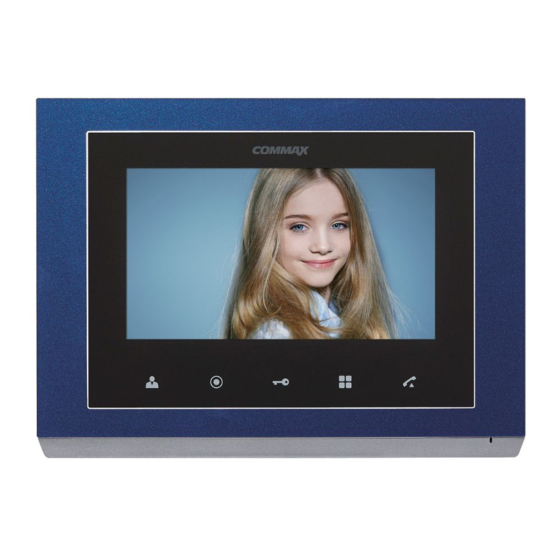
3. Part names Part name Part name Part name 7” TFTLCD Speaker Monitoring button Guard and Door release button Menu button(touch) interphone button Talk button C-MIC Menu button(side) △ button ▽ button 10 Enter button 13 Power ON/OFF Connecting terminals... -
Page 5: Operation
4. Operation 4-1 Functions for single & MODUM system 4-1-1 Use for single system 1) Communicate with visitor (1) Communicate in Monitor ① As the paging button on a door camera is pressed, the paging tone rings at the connected videophone and the visitor’s figure appears on the monitor. ②... - Page 6 3) Monitoring ① Press the “Monitoring button” in standby mode, you can check the image in order. - Camera 1 → Camera 2 → OFF → Camera 1 → repeat ② Press “Call” button during monitoring to call to the entrance. 4-1-2 Use for MODUM system - This function is only for MODUM system.
- Page 7 2) Communication with a guard (1) Receive a call ① The paging tone rings when receive a call from guard station. ② Press “Call” button to communicate. ③ When it receive any paging from an individual door camera, the paging tone rings and press “Monitoring”...
- Page 8 - Press “Door release” button to monitor CCTV when OSD menu appears on screen. : When the CCTV monitoring mode is selected, the additional select menu displays on screen. Press “Call” button to finish it. (Refer to description below to select CCTV for monitoring.) - Additional CCTV selection menu (1) When 1 unit of CMD-104VU is installed,...
- Page 9 (2) When 2 units of CMD-104VU are installed : The ▷ mark will be shown with port number and you can move on the next page. (Up to 8 ports, No. 1-8) : According to ID setting of CMD-104VU, ID 1 of CMV-104VU will be connected with port No.
-
Page 10: Settings
5. Settings - Press “Menu” button in video call or monitoring mode then Setting OSD will be shown on screen. - Both front touch keys and side switches can be used for settings as below. 1) Side switches - Start and finish menu : ⑨ MENU button - Select and input : ⑩... - Page 11 - OSD will be changed as below when select any menu. 5-1 DOOR VIDEO SET (Control the display) 1) BRIGHTNESS : select 0~20, defaults 10 2) CONTRAST : select 0~20, defaults 10 3) COLOR : select 0~20, defaults 10 - Settings for Brightness / Contrast / Color (1) Use “Move”...
- Page 12 ※ Setting - ZOOM : 4: 3 ratio’s image is enlarged to fill the screen. (defaults value) - 4:3 : the actual ratio of the image from camera. - WIDE : 16:9 ratio’s image is enlarged to fill the screen. 4) EXIT : Press “Select”...
-
Page 13: Initialization
6. Initialization - As “Interphone” and “Door release” buttons are pressed, at the same time, more than 3 seconds in standby mode, the initialization will be progressed with “Beep-Beep-Beep” sounds. - Please note that all information and screen mode are initialized with this progress. 7. - Page 14 ▷ Camera ※ Note ● Do not install a door camera in the area exposed to direct sunlight or backlight. ● Please keep the lens clean for the clearest image reflection.
-
Page 15: Wiring Diagram
8. Wiring Diagram ※ If you connect with MODUM system, you need to connect with 'CAMERA2' ports and floor distributor(Please refer to the manual of floor distributor for wiring.) Warning : - If you connect with a floor distributor(to connect with lobby or guard station), you have to connect with only 'CAMERA2' port.(If you connect with 'CAMERA1' port and floor distributor, it will not be operated normally. -
Page 17: Product Components
4P(3EA) ① Monitor(CMV-70S) ......1EA ② Wall bracket for monitor ..... .1EA ③... -
Page 18: Specifications
10. Specifications CMV-70S Camera 4-wire (Polarity, CAM2 will be convertible with Wiring type MODUM system) Inperphone 4-wire (Polarity) Power 100V-240V~, 50/60Hz Power Consumption Stand by : 4 W Max : 12 W Communication method HANDS FREE type (Voice switch circuit) Monitor 7″... - Page 19 Memo...
- Page 20 Memo...
- Page 21 513-11, Sangdaewon-dong, Jungwon-gu, Seongnam-si, Gyeonggi-do, Korea Int’l Business Dept. Tel. : +82-31-7393-540~550 Fax. : +82-31-745-2133 Web site : www.commax.com PM5470S00010 Printed In Korea / 2015.03.104...
- Page 22 User Manual Color Video Door Phone CMV 70S • Thank you for purchasing COMMAX products. Thank you for purchasing COMMAX products. • Please carefully read this User’s Guide (in particular, precautions for safety) before using a product and follow Please carefully read this User’s Guide (in particular, precautions for safety) before using a product and follow instructions to use a product exactly.
Need help?
Do you have a question about the CMV-70S and is the answer not in the manual?
Questions and answers