Table of Contents
Advertisement
Quick Links
Advertisement
Table of Contents

Subscribe to Our Youtube Channel
Related Manuals for Commax CMP-CTS


Summary of Contents for Commax CMP-CTS
- Page 1 User Manual https://aros.kz Lobby Camera Phone CMP-CTS, CMP-CTS/RF1...
-
Page 2: Table Of Contents
36. Part list ...........................59 37. Specifications and Features ....................60 38. RF-ID Model (Optional) ......................60 1. Greeting * Thank you for purchasing a COMMAX product * This product is a high tech Main Entrance interphone that supports electronic Please read this manual carefully. -
Page 3: Safety Warning & Caution
2. Safety Warning & Caution Please follow the things described below in order to prevent any danger or property damage. Prohibition. Warning It may cause a serious damage or No disassembly injury if violated. No touch Must follow strictly. Caution Shows plugging out the power cord It may cause a minor damage or without an exception... - Page 4 Warning Please don’ t disassemble, If an abnormal sound, burning Please don’t insert any Please use only the designated repair or rebuild this product smell or smoke is coming out metallic or burnable materials batteries for the products of of the product, please plug out arbitrarily (please contact the into the ventilation hole.
-
Page 5: Parts
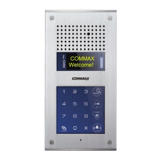
3. Parts 3-1. The name of parts Function Function Camera C-MIC OLED Display Extension Port RFID card receiver Wire Connection Port Number & Function Button... - Page 6 3-2. Important function ✽ Starting OLED display (Power ON OLED display) - If you want to display the method of lobby phone, Press the "P"(program button) hold over 5 seconds. ✽ RF/ID Receiver ③ (Optional) When open door by wireless card key, please tag it to this OLED display. (See bellow photo).
- Page 7 ✽ Electric key & UP Button (K : Key) 1) Open door by Password Number. (Deactivate Password LOCK function only.) 2) Move Up(In Program Mode) ✽ Cancel Button (X : Cancel) When user wants to cancel function, press it. ✽ Guard & Down Button (G : Guard) ✽...
- Page 8 ✽ Reset Button Reset security guard password or management office password. When forgot password, press reset Button which is on back side of products 15 (Press & Hold over 3 sec. after power on) ✽ Must know before use. 1) If you hear "beep beep beep..." during any Program modes, please restart from the beginning.
-
Page 9: Password Type
4. Password type 4-1. Password for the Management Office ("Management Password") A password for the Manager Factory default for the Manager Password is 4321. 4-2. Password for any buildings ("Building Password") A common password for a corresponding building. Factory default for the Building Password is 1234. 4-3. -
Page 10: How To Input Password
5. How to input Password 5-1. Press management Password • P - old Password - E - 0 - E - New Password - E • Password must be 4 digits. •"0000", "1234", "4321" can't be used as Password ① Press Program Button "P". ②... - Page 11 5-2. Press building Password • P - old Password - E - 1 - E - New Password - E • Password must be 4 digits. • "0000", "1234", "4321" can't be used as Password ① Press Program Button "P". ②...
- Page 12 5-3. Press house (Unit) Password • K - 20 - E- house Number - E- old Password - E - New Password - E • Password must be 4 digits. • "0000", "1234", "4321" can't be used as Password • Unit Password no. may not be changed because of Interphone types. (Some model of Interphone can change Password in house.
-
Page 13: Check House Password
6. Check house Password 6-1. Check house Password • P - management Password - E - 16 - E - Household Unit Number - E ① Press Program Button "P". ② Press management Password. ③ Press Call Button "E". ④ Press "16" (Program Number). ⑤... -
Page 14: Set Building Number And Id To Lobby Panel
7. Set building Number and ID to Lobby panel • This setting is mandatory because building Number and ID automatically are set up when lobby panel Call house and security guard. • Max. 99 lobby panel can be installed for one building. ①... - Page 15 7-2. Set ID no. in Lobby Panel • P - Management Password - E - 3 - E - ID - E ① Press Program Button "P". ② Press management Password. ③ Press Call Button "E". ④ Press "3" (Program Number). ⑤...
-
Page 16: Setting The Direct Call Option
8. Setting the Direct Call option • P - Management Password - E - 24 - E - 0 - E : Direct Call number only • P- Management Password - E - 24 - E - 1 - E : Direct Call number + Call button •... -
Page 17: How To Set The Direct Call Number
9. How to set the direct Call number • P - Management Password - E - 4 - E - Household number - E • This function is to set the direct call number ① Press Program Button "P". ② Press Management Passwords. ③... -
Page 18: Rf Card Key Appliances
10. RF card key appliances 10-1. RF card key test way • P- Management Password - E - 9 - E - Card Test - X(Cancel) • This function is only for the test of wireless card key ① Press Program Button "P". ②... - Page 19 10-2. RF card key input way • P- Management Password - E - 10 - E - Place card close to the RF/ID receiver - X(cancel) <References> Up to 2048 cards can be registered(if not to connect with SecuMAX)
- Page 20 10-3-1. RF card key separate deletion way • P- Management Password - E - 12 - E - Delete cards - X(Cancel) ① Press Program Button "P". ② Press Management Password ③ Press Call Button "E". ④ Press number "12" (Program Number). ⑤...
- Page 21 10-3-2. RF card key separate deletion way • P - Management Password - E - 12 - E - Identification number - X(Cancel) ① Press Program Button "P". ② Press Management Password ③ Press Call Button "E". ④ Press number "12" (Program Number). ⑤...
- Page 22 10-4. RF card key registration check way • P - Management Password - E - 13 - E - Delete cards - X(Cancel) ① Press Program Button "P". ② Press Management Password ③ Press Call Button "E". ④ Press number "13" (Program Number). ⑤...
- Page 23 10-5. RF card key all delete way • P- Management password - E - 11 - E - E • All deletion way is only useful when initially set up, unless all registered cards are to be deleted. ① Press down "P" Button ②...
- Page 24 10-6. RF card key capacity change way • P- Management password - E - 19 - E - 0 - E : Up to 2048 RF Cards can be registered • P- Management password - E - 19 - E - 1 - E : Unlimited RF Cards can be registered ) ①...
- Page 25 10-7. RF card key data transmission • P - Management Passwords - E - 32 - E - Press destination lobby phone number - E ① Press Program Button "P". ② Press Management password ③ Press Call Button "E". ④ Press number "32" (Program Number). ⑤...
- Page 26 10-8. RF card key data reception • P - Management Passwords - E - 33 - E - Press source lobby phone number - E ① Press Program Button "P". ② Press Management password ③ Press Call Button "E". ④ Press number "33" (Program Number). ⑤...
-
Page 27: Door Release By Internal Information Forwarding To Secumax Way
11. Door release by internal information forwarding to SecuMAX way •P - Management password - E - 22 - E - 0 - E : Forwarding to SecuMAX disabled •P - Management password - E - 22 - E - 1 - E : Forwarding to SecuMAX enabled •This function is to set the door release by internal sensor information forwarding to SecuMAX. -
Page 28: Door Opening Hours Setting
12. Door opening hours setting •P- Management Passwords - E- 5 - E - Opening hours - E •This function is to control the common entrance door opening hours. ① Press Program Button "P". ② Press Management Passwords ③ Press Call Button "E". ④... -
Page 29: Line-By-Line Call Function Setting
13. Line-by-line Call function Setting •P - Management password - E - 21 - E - 0 - E : available for entire house call •P - Management password - E - 21 - E - Line number - E : Call only specified line ex) In case 1 line ~ 2 line, input "0102". -
Page 30: Call Tones Selection
14. Call Tones selection •P - Management password - E - 7 - E - 0 - E : Melody sound •P - Management password - E - 7 - E - 1 - E : Bell(Ringer sound) •This function is to set the recall sound of house & guard station at the common entrance. ①... -
Page 31: Setting The Number Of Call Ring Repetitions
15. Setting the Number of Call Ring Repetitions •P - Management Password - E - 25 - E - 0 - E : Continuous call ring enabled. •P - Management Password - E - 25 - E - 1 - E : 1 time call ring enabled. •This function sets number of call ring repetition when a call is made to any households or security office. -
Page 32: Door Release By External Information Forwarding To Secumax Way
16. Door release by external information forwarding to SecuMAX way •P - Management password - E - 18 - E - 0 - E : Forwarding to SecuMAX disabled •P - Management password - E - 18 - E - 1 - E : Forwarding to SecuMAX enabled •This function is to set door release by external sensor information forwarding to SecuMAX ①... -
Page 33: Set To Be Forced Opening The Main Entrance Door By Secumax
17. Set to be forced opening the Main Entrance door by SecuMAX •P - Management password - E - 29 - E - 0 - E : Forced opening by SecuMAX disabled •P - Management password - E - 29 - E - 1 - E : Forced opening by SecuMAX enabled •This function is to set the opening the Main Entrance door forced opening by SecuMAX ①... -
Page 34: Selecting The Wiring Method
18. Selecting the Wiring Method •P - Management Password - E - 6 - E - 4 - E : common 4 wire method •P - Management Password - E - 6 - E - 6 - E : common 6 wire method •If common 6 wire method selected, there will be no video signal sent to all household units. -
Page 35: How To Set The Video Floor Distributor(Or Cdv Converter) Data
19. How to set the Video Floor Distributor (or CDV Converter) data •P - Management Password - E - 36 - E - Module ID - E - Setting the data - P •This function is to set household data of the video floor distributor or CDV converter when it is installed. - Page 36 ① Press Program Button "P". ② Press Management password. ③ Press Call Button "E". ④ Press "36" (Program Number). ⑤ Press Call Button "E". ⑥ Enter the Module ID. ⑦ Enter the household number, password and Monitoring Lobby ID. - If you want to move cursor, Press the Searching Button(S) ⑧...
-
Page 37: Video Out Impedance Adjustment Setting
20. Video Out Impedance Adjustment Setting •P - Management Password - E - 8 - E - 0 - E : Short distance transmission. •P - Management Password - E - 8 - E - 1 - E : Long distance transmission. •Factory default is set as "short distance transmission". -
Page 38: Registration Of Household Unit Number
21. Registration of Household Unit Number •P - Management Password - E - 15 - E - Call Security from the monitor.- number of household - E - serial number - E •This method applies to the case that there is no security station installed. Calling security from the monitor will direct the call to the lobby phone. - Page 39 ① Press Program Button "P". ② Press Management password. ③ Press Call Button "E". ④ Press "15" (Program Number). ⑤ Press Call Button "E". ⑥ From a household unit, Call security. The factory default household unit number appears on the OLED display of the lobby phone. Please Press the actual unit number. ⑦...
-
Page 40: Checking Videophone Status Of Household Units
22. Checking Videophone Status of Household Units •P - Management password - E - 14 - Unit Number - E - serial number - E •This function is to check the status of videophones installed in each household unit. - Page 41 ① Press Program Button "P". ② Press Management Password. ③ Press Call Button "E". ④ Press "14" (Program Number). ⑤ Press Call Button "E". ⑥ Press the Unit Number and press Call Button "E". ⑦ Press "0" (number zero as Master lobby phone or Press a corresponding lobby phone number) and press Call Button "E".
-
Page 42: Setting The Keypad Led Option
23. Setting the Keypad LED Option •P - Management Password - E - 20 - 0 - E : Keypad LED OFF? •P - Management Password - E - 20 - 1 - E : Keypad LED ON •This function is to set keypad LED ON/OFF. ①... -
Page 43: Activation Of Electronic Key (Password) Function
24. Activation of Electronic Key (Password) Function •P - Management Password - E - 31 - 1 - E : Electronic Key (Password) enabled. •P - Management Password - E - 31 - 0 - E : Electronic Key (Password) disabled. •This function is to enable or disable the password access. -
Page 44: Setting The Volume Of Voice And Beep Sound
25. Setting the Volume of Voice and Beep Sound •P - Management Password - E - 30 - E - Beep Volume (1~2) - Voice Volume (1~7) - E •This function enables the adjustment of Beep & Voice volume. ① Press Program Button "P". ②... -
Page 45: Method Of Name Data Sending
26. Method of name data sending •P - Management Password - E - 34 - E - Press destination lobby phone number - E ① Press Program Button "P". ② Press Management Password. ③ Press Call Button "E". ④ Press number "34" (Program Number). ⑤... -
Page 46: How To Receive The Name Of The Data
27. How to receive the name of the data •P - Management Password - E - 35 - E - Press source lobby phone number - E ① Press Program Button "P". ② Press Management Password. ③ Press Call Button "E". ④... -
Page 47: How To Set The Audio Floor Distributor Data
28. How to set the Audio Floor Distributor data •P - Management Password - E - 36 - E - Module ID - E - Setting the data - P •This function is to set household data of the audio floor distributor when it is installed. •Please, Refer to the manual of audio floor distributor if you want to know about more detailed functions. - Page 48 ① Press Program Button "P". ② Press Management password. ③ Press Call Button "E". ④ Press "36" (Program Number). ⑤ Press Call Button "E". ⑥ Enter the Module ID. ⑦ Enter the household number, password and DTMF setting value. - If you want to move cursor, Press the Searching Button(S). ⑧...
-
Page 49: Setting The Door Release By Building Password
29. Setting the door release by building password 29-1. Setting the Door Release by Building Password (Refer to 4-2) • "P" - Management Password - "E" - 28 (number twenty-eight) - 1 (number one) -"E": Door release by Building Password enabled. •"P"... - Page 50 29-2. Using a door release by Building Password function.
-
Page 51: When You Want To Call A Household
30. When you want to Call a household 1) Called to a household 2) Call by Direct call number If Program '24' is set by '0'... - Page 52 If Program '24' is set by '1' 3) Call by searching name...
-
Page 53: When You Want To Call A Guard Station
31. When you want to Call a Guard Station 1) Call by Searching name 2) Call by Guard Button... -
Page 54: Door Release By Unit Password
32. Door Release by Unit Password... -
Page 55: Supplement (Summary Of Various Programs)
33. Supplement (summary of various Programs) Setting Passwords 1. P–Previous Management Password–E–0–E– New Management Password–E: Management Password Registration. 2. P-Previous Building Password-E-1-E-New Building Password-E : Building Password Registration 3. K-20-E-Household Unit Number-E-Previous Unit Password-E-New Unit Password-E : Unit Password Registration 4. - Page 56 3. P-Management Password-E-29-E : Set to be forced opening the Main Entrance door by SecuMAX. Door Release by Password 1. Unit Number-K-Unit Password-E : by Unit Password. 2. E-Building Password : by Building Password How to make a unit Call and guard station Call from a lobby phone 1.
-
Page 57: Wiring Information
34. Wiring Information 1) Guard interphone ① GateView Guard Station ② 481 Guard Station... - Page 58 ③ Sensor connection method ④ Extension Panel <Caution> You can use both 2 and 4 rows panel(CMP-2BX/4BX) for extending but • can’t use together. (MAX. 5 units)
- Page 59 ⑤ Entrance interphone (CMP-CTS) ⑥ System schematic...
-
Page 60: Install Information
35. Install Information <Caution> 1) If installed outdoor, it requires extra molding for water-proof and • rainshield. 2) Recommanded height is pertinent from 1450mm ~ 1500mm 36. Part list Item Description Q’ty CONN. 2PX300 Wiring Connector CONN.3P(3.96)X250 Wiring Connector CONN.3PX300 Wiring Connector CONN. -
Page 61: Specifications And Features
37. Specifications and Features Installation Flush Mount Type installation Model CMP-CTS Gateview System (UTP Cable) Household unit monitor (8 wires-common 6 Wiring wires+video 2 wires), Security station phone (common 4 wires) Power Source DC 12V, 1A Power Consumption Standby : 82mA, Maximum : 276mA...
Need help?
Do you have a question about the CMP-CTS and is the answer not in the manual?
Questions and answers