Table of Contents
Advertisement
Quick Links
Please read all instructions before installing
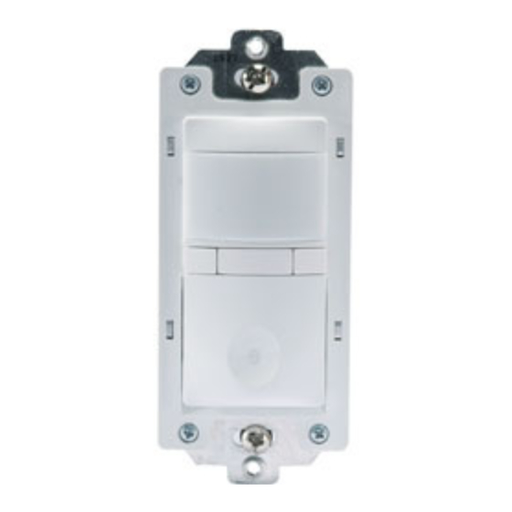
Multi-way Dimming Wall Switch
Lens
Air Gap Isolation Switch
Lighted Switch
ON/OFF/DIM button
SPECIFICATIONS
Voltage ............................................................... 120VAC, 60Hz
Load (Multi-way) ...................................................25-500 Watt
Compatibility ........................................................Incandescent
Time Delay Adjustment ...................15 seconds to 30 minutes
Environment .................................Residential Indoor use only
Operating Temperature .................. 32° to 104°F (0° to 40°C)
Humidity ......................................... 95% RH, non-condensing
Electrical Supply Wire Requirement
Minimum temperature rating ............................ 75°C (167°F)
Tools Needed .............. Insulated Screwdriver, Wire Strippers
DESCRIPTION AND OPERATION
The CD-250 Multi-way Dimming Wall Switch Vacancy Sensor is designed to
replace a standard single pole or multi-way (3-way, 4-way) switch or dimmer. It
is ideal for living and dining rooms, family rooms, bedrooms, bathrooms and any
other indoor area in a residential space where occupancy sensor-based manual
ON/OFF and Dimming control is desirable.
Like a standard switch, you press the ON/OFF/DIM button to turn the dimmable
lighting load ON and OFF. Unlike a standard switch, the CD-250 automatically
turns OFF the controlled load after the coverage area has been vacant for a
period of time (Time Delay). If motion is detected within 30 seconds after it
automatically turns OFF, the CD-250 automatically turns the load back ON. Like
a standard dimmer, once the lighting load is ON, you can dim it UP or DOWN by
pushing and holding the ON/OFF/DIM button. When you push the ON/OFF/DIM
button to turn the dimmable load ON, the CD-250 recalls the last used dimming
level.
The CD-250 can be wired with up to 3 additional CD-250s for multi-way Manual-
ON/OFF, Auto-OFF of one or several loads (up to one load connected to each CD-
250). It can also be wired to up to 4 RH-253 single pole momentary wall switches
for multi-way Manual-ON/OFF Automatic-OFF control of one load.
Lighted Switch
To help you locate the CD-250 in a dark room, the amber LED illuminates the ON/
OFF/DIM button while the controlled load is OFF. When the controlled load is ON,
the LED is OFF.
The lighted switch ON/OFF/DIM button can be used to manually turn ON and OFF
the lighting load and to dim it UP and DOWN.
To turn the load ON, tap fi rmly on the ON/OFF/DIM button once. The amber LED
turns OFF and the load turns ON to the last used dimming level. The lighting load
may or may not appear to be ON depending on how low the lights were set the
last time they were dimmed.
Once the load has been turned ON, push and hold the ON/OFF/DIM button to dim
the lights UP or DOWN. To reverse the dimming direction momentarily release
the ON/OFF/DIM button, then push and hold it again. This feature will allow you
to reach the desired dimming level quicker.
Call 888.817.0571 for Technical Support
CD-250
Vacancy Sensor
Santa Clara, CA 95050
Advertisement
Table of Contents

Subscribe to Our Youtube Channel
Related Manuals for Watt Stopper CD-250


Summary of Contents for Watt Stopper CD-250
- Page 1 Manual-ON/OFF Automatic-OFF control of one load. Lighted Switch To help you locate the CD-250 in a dark room, the amber LED illuminates the ON/ OFF/DIM button while the controlled load is OFF. When the controlled load is ON, the LED is OFF.
- Page 2 fl uorescent lighting fi xture, or a transformer-supplied appliance. Disconnect power to the wall switch box by turning OFF the circuit breaker or removing the fuse for the circuit before installing the CD-250, replacing lamps, or doing any electrical work. www.wattstopper.com/athome...
- Page 3 Fig. 4a: Sensor orientation, single pole • Connect the power wire to wire connections and wall box the lamp (LOAD) to the red wire on assembly the CD-250. • Cap the yellow wire on the CD-250. It is not used in single pole applications.
- Page 4 • Connect the power wire from the circuit box (HOT) to the black wire on the auxiliary CD-250 and to the TRAVELER 1 wire. • Connect the TRAVELER 1 wire from the black wire of the auxiliary CD-250 to the black wire of the master CD-250.
- Page 5 4. Repeat as necessary to ensure that the desired coverage areas are within detection range. You can do this test for each CD-250 in your multi-way confi guration. So that you can determine the actual coverage area for each multi-way switch...
- Page 6 2. After replacing the lamp(s), press the Air Gap Switch so that it returns to a position that is fl ush with the surface of the rest of the CD-250. This allows the dimming sensor to control the lighting load correctly.
Need help?
Do you have a question about the CD-250 and is the answer not in the manual?
Questions and answers