Advertisement
INSTRUCTION MANUAL
MODBUS INTERFACE MODULE
BEFORE USE ....
Thank you for choosing M-System. Before use, please check
contents of the package you received as outlined below.
If you have any problems or questions with the product,
please contact M-System's Sales Office or representatives.
■ PACKAGE INCLUDES:
Network interface module ............................................ (1)
Terminating resistor (110Ω, 0.25W) ............................ (1)
■ MODEL NO.
Confirm Model No. marking on the product to be exactly
what you ordered.
■ INSTRUCTION MANUAL
This manual describes necessary points of caution when
you use this product, including installation, connection and
basic maintenance procedures.
POINTS OF CAUTION
■ CONFORMITY WITH EC DIRECTIVES
• The equipment must be mounted inside the instrument
panel of a metal enclosure.
• The actual installation environments such as panel con-
figurations, connected devices and connected wires may
affect the protection level of this unit when it is integrated
in a panel system. The user may have to review the CE
requirements in regard to the whole system and employ
additional protective measures to ensure CE conformity.
■ POWER INPUT RATING & OPERATIONAL RANGE
Locate the power input rating marked on the product and
confirm its operational range as indicated below:
100 – 120V AC rating: 85 – 132V, 47 – 66 Hz, approx. 20VA
200 – 240V AC rating: 170 – 264V, 47 – 66 Hz, approx. 20VA
24V DC rating: 24V ±10%, approx. 12W
■ GENERAL PRECAUTIONS
Before you remove the unit from its base or mount it, turn
off the power supply for safety.
■ ENVIRONMENT
• Indoor use
• When heavy dust or metal particles are present in the air,
install the unit inside proper housing with sufficient ven-
tilation.
• Do not install the unit where it is subjected to continuous
vibration. Do not subject the unit to physical impact.
• Environmental temperature must be within -10 to +55°C
(14 to 131°F) with relative humidity within 30 to 90% RH
in order to ensure adequate life span and operation.
■ WIRING
• Do not install cables (power supply, input and output)
close to noise sources (relay drive cable, high frequency
line, etc.).
• Do not bind these cables together with those in which
noises are present. Do not install them in the same duct.
MODEL
■ AND ....
The unit is designed to function as soon as power is sup-
plied, however, a warm up for 10 minutes is required for sat-
isfying complete performance described in the data sheet.
INSTALLATION
Use the Installation Base Model R3-BSx, or Model R3-
BSWx for free I/O address capability.
Before mounting the Network Interface Module onto the
Base, be sure to configure the module as explained below.
■ DATA ALLOCATION
The setting determines the data area size assigned to each
I/O module mounted on the base.
The data sent/received via Modbus is mapped according to
this setting.
See "DATA DESCRIPTION" in Page 4.
■ NODE ADDRESS
See "COMPONENT IDENTIFICATION" in Page 2.
■ NETWORK SLOTS ON THE BASE
I/O 1
I/O 2
With Model R3-BSx base, mount the I/O Modules from the
left end (I/O 1) to the right in order that the Network Mod-
ule assigns data areas from I/O 1.
Network Module(s) and Power Module are mounted basi-
cally at the right end though technically they could be
mounted in any position.
With Model R3-BSWx base, there is no limitation in mount-
ing positions as I/O address can be assigned freely to each
module using rotary switches equipped on the base.
R3-NM1
R3-NM1
I/O n
EM-8354 Rev.4
P. / 7
Advertisement
Table of Contents

Related Manuals for M-system R3-NM1


Summary of Contents for M-system R3-NM1
- Page 1 The unit is designed to function as soon as power is sup- plied, however, a warm up for 10 minutes is required for sat- Thank you for choosing M-System. Before use, please check isfying complete performance described in the data sheet.
-
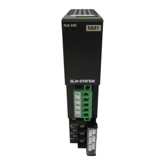
Page 2: Component Identification
R3-NM1 COMPONENT IDENTIFICATION ■ FRONT VIEW ■ SIDE VIEW Node Address (MSD) RUN LED Node Address (LSD) ERR LED Functions Transmission Properties Configuration Jack Terminal Block ■ FRONT ROTARY SW SW ASSIGNMENT SLOT Set the module’s node address in hexadecimal with SA1 and SA2. -
Page 3: Terminal Connections
R3-NM1 • LED Function: SW3 • Main/Sub Switching Control: SW3 Functions assigned to the front RUN and ERR LEDs can The host PC or PLC can choose whether ‘Main’ or ‘Sub’ bus be selected. is used when the switching control is set to ‘Host.’... - Page 4 R3-NM1 MODBUS FUNCTION CODES & SUPPORTED CODES ■ DATA & CONTROL FUNCTIONS CODE NAME R3-NM1 Read Coil Status Digital output from the slave (read/write) Read Input Status Status of digital inputs to the slave (read only) Read Holding Registers General purpose register within the slave (read/write)
-
Page 5: Modbus I/O Assignments
R3-NM1 MODBUS I/O ASSIGNMENTS ADDRESS DATA FORMAT NAME Coil (0X) 1 – 1024 Digital Output (discrete output) 1025 Main / Sub Switching Command (valid only with SW3-3 set to ON) Inputs (1X) 1 – 1024 Digital Input (discrete input) 1025 – 1040 Module Status 1041 –... - Page 6 R3-NM1 I/O DATA DESCRIPTIONS ■ MODULE STATUS, ERROR STATUS, DATA ERROR STATUS Shows each module’s availability and error status. Module 1 Module 2 Module 3 Module 16 ■ ANALOG DATA (models: R3-SV4, YV4, DS4, YS4 and US4) 16-bit binary data.
- Page 7 R3-NM1 ■ DISCRETE DATA (models: R3-DA16 and DC16) Input 1 (Output 1) Input 2 (Output 2) Input 3 (Output 3) Input 16 (Output 16) 0 : OFF (open) 1 : ON (close) ■ MAIN / SUB SWITCHING CONTROL R3 main network...
Need help?
Do you have a question about the R3-NM1 and is the answer not in the manual?
Questions and answers