
Related Manuals for Marshall Electronics CV620-BK


Summary of Contents for Marshall Electronics CV620-BK
- Page 1 Marshall Electronics CV620-WH & CV620-BK Full HD Broadcast PTZ Camera Installation Guide Ver.3...
-
Page 2: Table Of Contents
I would like to adjust the shooting angle of the lens......28 I would like to zoom in/out images ........... 28 I would like to adjust the focal length ..........29 I would like to adjust the focus speed ..........29 Marshall Electronics... - Page 3 6.11 I would like to rotate the image............30 6.12 I would like to change the camera direction ........30 6.13 I would like to display the current status .......... 30 DIP Switch Setting................... 31 DIP SWITCH ..................31 RS-422 Connection ................33 Troubleshooting ....................35 Marshall Electronics...
-
Page 4: Safety Instructions
If the power cable or plug becomes damaged or frayed. If the camera is wet with liquid, rain or water. * Note Using an incorrect battery type in the remote control may result in breakdown. Follow local instructions on how to dispose of used batteries. Marshall Electronics... -
Page 5: Precautions
Cet appareil numerique respecte les limites de bruits radioelectriques applicables aux appareils numeriques de Classe A prescrites dans la norme sur le material brouilleur: "Appareils Numeriques," NMB-003 edictee par l'Industrie. EN55032 (CE Radiation) Warning Operation of this equipment in a residential environment could cause radio interference. Marshall Electronics... -
Page 6: Package Contents
Package Contents Instruction for CV620 Remote Control installation Power Cord Power Adapter RS-422 Connector Appearance may vary depending on country/region Metal Plate A Metal Plate B M3 Screws Marshall Electronics... -
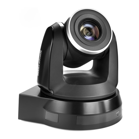
Page 7: Product Overview
No light: Power off 3.2.1.1 Green light: In use 3.2.1.2 Flickering green: Signal from the remote control is received; 3.2.1.3 the indicator flickers every 0.5 second 3.2.2 Standby: Orange: In standby mode 3.2.2.1 No light: Power on 3.2.2.2 Marshall Electronics... -
Page 8: Instruction For Installation
Please install the machine on a flat desk Do not grab the camera head by hand when handling the device Do not rotate the camera head by hand. Improper rotation may result in breakdown of the camera Marshall Electronics... - Page 9 1. Accessories of CV620 in the box (metal plates A, B and M3 screw x 7) 2. Screw for locking on ceiling mounted hanger x 4 3. Drilling machine, screw driver, ladder 4.2.2.2 Dimension Length x Width x Height: 174x186.13x185.88. Weight: 2.0Kg Marshall Electronics...
- Page 10 4.2.2.3 Max. rotation dimension of camera Marshall Electronics...
- Page 11 4.2.2.4 Size Diagram 1. Metal plate B - ceiling side Metal plate B locking screw Metal plate B locking bolt M3 threaded hole M3 threaded M3 threaded hole hole Metal plate B - ceiling side Marshall Electronics...
- Page 12 2. Metal plate A - machine side Metal plate A locking screw Metal plate A - machine side Marshall Electronics...
- Page 13 3. Bottom of camera Marshall Electronics...
- Page 14 1. Please adjust resolution on DIP switch at first * Please refer to Chapter 7 DIP Switch Setting for the relevant descriptions on DIP switch. 2. Fix the metal plate A on the machine base with 4 M3 screws. Marshall Electronics...
- Page 15 4. Combine the metal plate A and the metal plate B (1) Push the metal plate A up to the ceiling and then to the right to latch the metal plate B (2) Secure with 2 M3 silver screws and 1 M3 black screw. 4.2.2.7 How to remove Marshall Electronics...
- Page 16 2. Uninstall the camera together with the ceiling, loosen the three screws that fix the metal plates A and B and push to the left to remove the machine 3. Remove the screws on the hanger and the machine Marshall Electronics...
-
Page 17: Connecting The Device
4.3 Connecting the device 4.3.1 Image output Connecting to a HDTV/computer monitor (DVI) 4.3.1.1 DVI cable Monitor HDTV Connecting to a TV (C-Video) 4.3.1.2 C-Video Cable Marshall Electronics... - Page 18 Connecting to a HDTV (3G-SDI) 4.3.1.3 SDI Cable HDTV Connection to the device for image output 4.3.1.4 Component adaptor HDTV Marshall Electronics...
- Page 19 * With RS-232 in/out, at most 7 CVs can be connected. Connecting several CV620s to one computer via RS-422/232 4.3.2.2 * Please refer to 7.2 RS-422 connection for the RS-422 connection instructions. * With RS-422, at most 7 CVs can be connected. Marshall Electronics...
-
Page 20: Remote Control And Setting Menu
B&W) Power Power switch Preset Appoint an ID (0 ~ 9) to save the current position data Reset Appoint an ID (0 ~ 9) to delete the current position data Zoom-Fast Adjust image size Zoom-Slow Fine-tune image size Marshall Electronics... -
Page 21: Setting Menu
Spot Light X(0~15)Y(0~15) only after Spot Light is Position activated 60/30 50/25 Shutter Shutter priority setting mode mode Priority 1/10000 1/10000 1/6000 1/6000 1/4000 1/3500 1/3000 1/2500 1/2000 1/1750 1/1500 1/1250 1/1000 1/1000 1/725 1/600 1/500 1/425 1/350 1/300 Marshall Electronics... - Page 22 1/50 1/30 1/25 1/15 1/12 1. F1.6 2. F2 3. F2.4 4. F2.8 5. F3.4 6. F4 7. F4.8 Iris Priority IRIS priority setting 8. F5.6 9. F6.8 10. F8 11. F9.6 12. F11 13. F14 14. Close Marshall Electronics...
- Page 23 Manually set the shutter mode mode 1/10000 1/10000 1/6000 1/6000 1/4000 1/3500 1/3000 1/2500 1/2000 1/1750 1/1500 1/1250 1/1000 1/1000 1/725 1/600 1/500 1/425 1/350 1/300 1/250 1/215 1/180 1/150 1/125 1/120 1/100 1/100 1/90 1/75 1/60 1/50 Marshall Electronics...
- Page 24 2. 13.7 dB 3. 17.1 dB 4. 20.5 dB 5. 23.9 dB 6. 27.3 dB The maximum electric Gain Limit 7. 30.7 dB gain limit 8. 34.1 dB 9. 37.5dB 10. 41dB 11. 44.4 dB 12. 47.8 dB Marshall Electronics...
- Page 25 Manual 1. Off Picture effect Set the picture effect Picture 2. Neg 3. B&W Adjust the sharpness of Sharpness 1~A~16 the image 1. Off 2. 1 3. 2 Set 2D noise reduction 4. 3 5. 4 6. 5 Marshall Electronics...
- Page 26 Tilt Flip command will be reversed 1. 5 deg/sec 2. 25 deg/sec Set the rotation speed of 3. 50 deg/sec the cradle head when Preset Speed 4. 150 deg/sec Preset is executed 5. 250 deg/sec 6. 300 deg/sec Marshall Electronics...
- Page 27 Language Control Encoder / Set control device Controller Device Protocol V / Protocol V: VISCA Protocol Protocol PD Protocol PD: PELCO D The Protocol set to PD 1~255 allows the camera ID PD Address address to be assigned Marshall Electronics...
- Page 28 6. 1920x1080/50i 7. 1280x720/60p Output Mode 8. 1280x720/50p 9. 1280x720/30p 10. 1280x720/25p 11. 1080/59.94p 12. 1080/59.94i 13. 1080/29.97p 14. 720/59.94p 15. 720/29.97p Reset all configurations to ON/Off Factory Reset factory default settings. Display the current setting Status status Marshall Electronics...
-
Page 29: Descriptions Of Major Functions
6.6 I would like to zoom in/out images 6.6.1 Adjust image size 1. Press [Fast +] on the remote control to zoom in images. 2. Press [Fast -] on the remote control to zoom out images. Marshall Electronics... -
Page 30: I Would Like To Adjust The Focal Length
[Normal] (default): Image flickering may not occur [1~5]: The focus speed is fast, but image flickering is more likely to occur 1. Press [MENU] to activate the setting menu. 2. Press [] or [] to select [Auto Focus]. Marshall Electronics... -
Page 31: I Would Like To Set The Image Mode
1. Press [L/R Direction Set] on the remote control to switch [L/R Direction / Off / Normal]. 6.13 I would like to display the current status 1. Press [Info] on the remote control to display the current status information. Marshall Electronics... -
Page 32: Dip Switch Setting
* Please turn off the machine before changing DIP switch setting. 7.1 DIP SWITCH 7.1.1 OUTPUT Switch Output Mode Setting Output Mode Setting 1920x1080/60p 1920x1080/50p 1920x1080/30p 1920x1080/25p 1920x1080/60i 1920x1080/50i 1280x720/60p 1280x720/50p 1280x720/30p 1280x720/25p 1920x1080/59.94p 1920x1080/59.94i 1920x1080/29.97p 1280x720/59.94p 1280x720/29.97p Marshall Electronics... - Page 33 DIP 1 OFF : RS-232C / ON : RS-422 Infrared signal output switch DIP 2 OFF : Off / ON : On Communication baud rate selector DIP 3 OFF : 9600 / ON : 38400 DIP 4 Reserved Marshall Electronics...
-
Page 34: Rs-422 Connection
7.2.2 Use RS-422 Connection 1. Hold the two sides of RS-422 connector and pull out in the direction shown by the arrow in the figure below 2. Peel off a section of copper wire (AWG Nos.28 to18) and insert it into Marshall Electronics... - Page 35 3. Insert the wired RS-422 connector back to the camera. Now the connection is completed * When RS-422 connection is being used, do not use RS-232C connection. Marshall Electronics...
-
Page 36: Troubleshooting
The steps to be controlled with check version is as follows: Codec 1.1 Press [MENU] on the remote control 1.2 Select [Status] 1.3 Go to Page 5 of [System] 1.4 Make sure the firmware version is correct Marshall Electronics... - Page 37 1. Make sure the connection is correct (RS-232/422 be controlled with Input). RS-232/RS422 2. Make sure System Switch DIP1 and DIP3 are correct. Marshall Electronics 20608 Madrona Avenue Torrance, CA 90503 Phone: (310) 333-0606 / (800) 800-6608 Fax: (310) 333-0688 www.marshall-usa.com...
Need help?
Do you have a question about the CV620-BK and is the answer not in the manual?
Questions and answers