Table of Contents
Advertisement
Quick Links
Advertisement
Table of Contents

Related Manuals for Marshall Electronics VS-570-HDSDI


Summary of Contents for Marshall Electronics VS-570-HDSDI
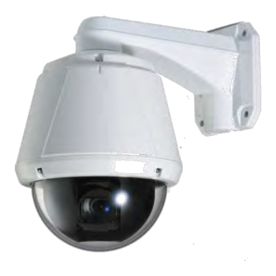
- Page 1 VS-570-HDSDI 2.0 Megapixel Speed Dome User Manual ver.1.0 v1.0 10062010570...
-
Page 2: Safety Precaution
We appreciate your purchasing VS-570-HDSDI. Before installing the product, please read the following with care Make sure to turn off the power before installing VS-570-HDSDI. Do not install under the direct sunlight or in dusty areas. Make sure to use the product within the temperature and humidity specified in the specification. -
Page 3: Table Of Contents
VS-570-HDSDI User Manual Table of Content 1. Introduction ..........................4 About this manual ........................4 Features ........................... 4 Product and Accessories ......................7 Part Names and Functions ....................... 8 System Connections ......................... 9 2. Installation ..........................12 DIP Switch Setup ........................12 Installation Camera with Brackets ................... -
Page 4: Introduction
HDSDI. The Manual includes instructions of installation, operation and configuration of VS-570-HDSDI troubleshooting tips. Features VS-570-HDSDI is a 2.0M PTZ network-based camera with remote live monitoring, audio monitoring and control via an IP network such as LAN, ADSL/VDSL, and Wireless LAN. Camera 1/3”... -
Page 5: User Interface
VS-570-HDSDI User Manual Serial Data RS-485 support: • Data pass-through mode: Serial data communication between VS-570-HDSDI and Decoder. • Sensor and Alarm Supports direct connections of external sensor and alarm devices. • Event Alarm notification. • 2 alarm sensor Inputs and 2 alarm Output relays are available. -
Page 6: Ptz Control
VS-570-HDSDI User Manual PTZ(Pan/Tilt/Zoom) Control With RS-485 communication, a maximum of 255 cameras can be controlled at the same time. • Pelco-D or Pelco-P protocol can be selected as a control protocol in the current version of • firmware. Easy Installation and Perfect Outdoor Environment Compatibility Fans and heaters are built into the camera enclosure for both hot and cold temperature •... -
Page 7: Product And Accessories
VS-570-HDSDI User Manual Product and Accessories Main body & Dome Cover Accessories Main Cable Wrench Driver 2EA of BNC Cross LAN Cable Audio Cable Note: Mount Brackets are optional. Wall Mount Bracket Ceiling Mount Bracket [Screws : Torx Screw M418, Hex Lag #1450] [Screws : Torx Screw M418, Anchor Bolt 3/8"70]... -
Page 8: Part Names And Functions
VS-570-HDSDI User Manual Part Names and Functions ① Dome Cover To protect the dome cover from scratches or dust Do Not Remove the • protective vinyl from the dome before completing the installation process. DIP Switch Sets up camera ID and protocol. -
Page 9: System Connections
Remote Center (PC SW) One VS-570-HDSDI is installed at a site where video images are transmitted. A PC or a decoder is installed at a central location to receive and view the video images on an analog monitor. Audio and serial data are transferred in either direction. -
Page 10: Multicast Mode
If the network supports multicasting, a large number of decoders can be used to receive video effectively from a VS-570-HDSDI using a single streaming of video and audio. However, multicast mode is possible only when the network environment supports multicast. - Page 11 VS-570-HDSDI User Manual CMS (Central Monitoring System) Remote Center Site Site Remote Center (Decoder) CMS (Central Monitoring System) is a Window-based remote monitoring program used to monitor or control video, audio, and events in real time from several IP cameras or video servers. Please refer to the CMS User Manual for more detail.
-
Page 12: Installation
VS-570-HDSDI User Manual 2. Installation DIP Switch Setup When you control the camera through RS-485, before installation, you should set the DIP switches to configure the camera ID, communication protocol. Camera ID setup ID numbers of each camera are set up using binary numbers. -
Page 13: Communication Protocol Setup
VS-570-HDSDI User Manual Communication Protocol Setup Select the appropriate Protocol with DIP switch combination. Switch State Protocol/Baud rate (Pin 1) (Pin 2) (Pin 3) PELCO-D, 2400 bps PELCO-D, 9600 bps PELCO-P, 4800 bps PELCO-P, 9600 bps Otherwise Reserved If you want to control using a DVR or P/T controller, their protocol must ... -
Page 14: Installation Camera With Brackets
VS-570-HDSDI User Manual Camera Installation using Brackets Installation using a Ceiling Mount Bracket (not supplied) ① Remove the ceiling tile from the ceiling and cut a ② Hook up the “Drop Prevention Spring” on main body hole whose diameter is 30~40mm on the ceiling tile to prevent the camera from unexpected drops. - Page 15 VS-570-HDSDI User Manual Installation using the Wall Mount Bracket ① Make a hole whose diameter is 30~40mm on ② Hook up the “Drop Prevention Spring” on main body to the mounting surface to pass the wire(s) and prevent the camera from unexpected drops. Pull the cable(s) through the mounting surface.
-
Page 16: Wiring/Cabling & Connecting
VS-570-HDSDI User Manual Wiring/Cabling & Connecting Port Description Main Cable Port Pin Number (RJ45) Connector / Wire Color Signal Black RS485 + Brown RS485 DC 12V Orange Ground Yellow OUT COM (Relay Output Common) Green OUT 2 (Relay Output 2) -
Page 17: Connecting Power
VS-570-HDSDI User Manual Connecting Power Carefully check the voltage and current capacity of the rated power. The rated power is indicated in the back of main unit. After confirming the voltage, connect the power adaptor to the AC power source then connect the 12V DC connector to the system . -
Page 18: Connecting Sensor And Alarm
A PC client can send PT commands to the external equipment via the serial port. When a decoder system instead of a PC client is connected to VS-570-HDSDI, the serial port and that of the decoder system work in pass-through mode. That is, data from one port is delivered to the other port and vice versa. -
Page 19: Check If It Works
VS-570-HDSDI User Manual Relay Output Internal AC or DC OUT COM OUT 1 LOAD OUT 2 LOAD Maximum allowable electrical load of relay is shown bellow table. Drive Power DC Power AC Power Max. Load Max DC 24V, 1A Max AC 125V, 0.5A... -
Page 20: System Operation
3. System Operation Remote Video Monitoring There are two ways to monitor video when the center system and VS-570-HDSDI are connected. In order for proper operation, an IP address must be set accordingly. Please refer to True Manager in Chapter 3 or Remote Setting in Chapter 4 for further details. - Page 21 Select the Video stream to be viewed: Primary or Secondary. The VS-570-HDSDI is capable of dual streaming; primary streaming and secondary streaming. Video will be displayed according to the resolution set in the video configuration. If dual streaming (“Use Dual Encode”...
- Page 22 Alarm Output Operates the alarm device by pressing the number icon VS-570-HDSDI supports two alarm outputs. A number icon indicates the status of the alarm device. Screen Capture Captures video images and stores them as BMP or JPEG files.
-
Page 23: Initialization Of Ip Address
VS-570-HDSDI User Manual Video Monitoring with Decoder System Once the VS-570-HDSDI‟s IP address is set in the remote IP address section of the decoder, the decoder system will connect to VS-570-HDSDI and start receiving the video images. Normally, a monitor connected to the decoder will display video images. -
Page 24: Remote Configuration
Using Web Brower Remote setting is available by using the web browser. Enter the IP address of a VS-570-HDSDI, a live view screen appears as below. Press the Setup button located in the upper right area of the monitoring screen to go to the server setup. -
Page 25: System Configuration
VS-570-HDSDI User Manual System Configuration 25/54 2.0 Megapixel Speed Dome Manual... - Page 26 Firmware version Displays the current firmware version. Board ID Display the Network board ID of VS-570-HDSDI recognized by system. Upgrade Upgrade firmware : Press the Browse button to select a firmware file from your PC. Press the Firmware Upgrade button to start the upgrade.
- Page 27 VS-570-HDSDI User Manual Time Start Time This is the date and time when the camera was last booted. Current Time This is the current date & time. Enter a new date and time and press the Set Current Time button to update.
-
Page 28: Factory Reset
VS-570-HDSDI User Manual Factory Reset This changes the Current IP Address of VS-570-HDSDI to default IP Address: 192.168.10.100. The System log and user registrations are also cleared. All other setting values will remain. Note that the Password will not be changed by the Factory Reset for the security purpose. Please contact Marshall Electronics Technical Support if you forget your password. -
Page 29: Video Configuration
VS-570-HDSDI User Manual Video Configuration 29/54 2.0 Megapixel Speed Dome Manual... - Page 30 VS-570-HDSDI User Manual Encode Enable Preview 1. Select ON to display video on the monitor that is connected to the composite or HD-SDI video port. 2. Select the Output format accordingly in the end of the Video page. Note that when Enable Preview is ON, dual streaming is not available.
- Page 31 VS-570-HDSDI User Manual Quality Select the required Video quality. Eight levels of quality are available. Quality mode (VBR encoding) adjusts the bit rate according to the image complexity, using higher bandwidth for increased activity in the video and lower bandwidth for decreased activity.
-
Page 32: Motion Detection
VS-570-HDSDI User Manual Dual Encode Use Dual Encode 1. Select the Off button on the Enable Preview to enable to use Dual Encode. 2. Select the ON button to enable to use Dual Encoding. The secondary video can be viewed on Live View window by selecting Secondary on Video selection. -
Page 33: Output Format
VS-570-HDSDI User Manual Sensitivity Sensitivity selects the amount of movement required to trigger (detect) a motion event. The value determines the sensitivity of the motion detection within a block. The lower the number the more sensitive to movement. Select from 0 to 10. -
Page 34: Audio Configuration
Select the Bitrate to be 64kbps or 128kbps when AAC is selected. The sampling rate is fixed to 32KHz when G7.11 is selected. Note that when VS-570-HDSDI is connected to a decoder, the decoder‟s audio algorithm MUST be set identically to transmit audio and video properly. -
Page 35: Network Configuration
VS-570-HDSDI User Manual Network Configuration 35/54 2.0 Megapixel Speed Dome Manual... - Page 36 VS-570-HDSDI User Manual Local IP mode Select the IP mode: Fixed IP or DHCP (Dynamic Host Configuration Protocol) Depending on the mode selected, configuration items will appear as follows: IP Mode Selection Description Local IP Fixed IP address Local...
- Page 37 VS-570-HDSDI User Manual HTTP Port Enter the HTTP port used for web-based connection. RTSP Port Enter the RTSP port used for RTSP-based connection. The default RTSP port is 554. RTSP (Real Time Streaming Protocol) is a standard for connected client(s) to control streaming data over the World Wide Web.
- Page 38 VS-570-HDSDI User Manual SNMP The VS-570-HDSDI can be used as an SNMP agent. It is compatible to both SNMPv1 and SNMPvec. Settings for using SNMP (Simple Network Management Protocol) are as follows: SNMP Listen Port: This port is used for connecting external devices when the system operates as an SNMP client.
- Page 39 VS-570-HDSDI User Manual Check IP Disable: If “Check IP Disable” is selected, the IP Server will skip to check its own IP. In Fixed IP mode, the set IP will be registered on the DDNS server. In DHCP mode, the allotted IP will be registered on the DDNS server.
-
Page 40: Serial Configuration
VS-570-HDSDI User Manual Serial Configuration 40/54 2.0 Megapixel Speed Dome Manual... -
Page 41: Serial Port Configuration
PTZ Type & ID: PTZ Type & ID are displayed automatically once the camera reboots after DIP switch setup. The default PTZ Type and ID is Pelco-D and 2400bps. Sensor Type There are two sensor input ports on VS-570-HDSDI. The sensor ports can be configured as follows: Function Operation Not used... -
Page 42: Event Configuration
VS-570-HDSDI User Manual Event Configuration 42/54 2.0 Megapixel Speed Dome Manual... - Page 43 The VS-570-HDSDI has two sensor ports and two alarm ports. When a decoder instead of a PC client is connected to a VS-570-HDSDI, one system becomes a Local system and the other a Remote system. Generally a system which is being used by the user is called the Local system.
-
Page 44: Ftp Upload
VS-570-HDSDI User Manual E-mail Notification Specifies the information required to send event information, when E-mail is selected as an event action. Server Address: Enter an address of a mail (SMTP) server. Port: Specify a port for SMTP operation. Port 25 is the default port in SMTP operation. If a different port is configured in the SMTP server, this port needs to be changed accordingly. -
Page 45: Ptz Configuration
VS-570-HDSDI User Manual PTZ Configuration 45/54 2.0 Megapixel Speed Dome Manual... - Page 46 VS-570-HDSDI User Manual Control PTZ using the PTZ controller Preset A Maximum 128 positions can be stored as Preset positions. 1. Move the position to be set. 2. Select one of the entries of Preset from the list.
- Page 47 VS-570-HDSDI User Manual Swing By using Swing function, you can make camera to move between 2 Preset positions repeatedly. When swing function runs, camera moves from the preset assigned as the 1st point to the preset assigned as the 2nd point in CW(Clockwise) direction. Then camera moves from the preset assigned as the 2nd point to the preset assigned as the 1st point in CCW(Counterclockwise) direction.
- Page 48 VS-570-HDSDI User Manual Ex) Group-1 Swing-1 Preset-1 Pattern-1 Repeat 2 Speed 3 Repeat100 Live View Page Select List-1 and Press Group to playback the Group-1 program. 48/54 2.0 Megapixel Speed Dome Manual...
-
Page 49: Record Configuration
VS-570-HDSDI User Manual Record Configuration This page is not available from the VS-570-HDSDI When using the VS-570-HDSDI the Record page is not available. 49/54 2.0 Megapixel Speed Dome Manual... -
Page 50: User Configuration
VS-570-HDSDI User Manual User Configuration User List Users can be registered and the privilege level of each user can be specified. User configuration is allowed only by the Admin user. A maximum of 16 users can be registered and each user can have... - Page 51 VS-570-HDSDI User Manual Delete User Select the User to be deleted and press the Delete button. Change Password Press Modify Password button. The following window will appear: Enter the current password and then set a new password. Modify Privilege Level ...
-
Page 52: Camera Configuration
VS-570-HDSDI User Manual Camera Configuration 52/54 2.0 Megapixel Speed Dome Manual... -
Page 53: White Balance
VS-570-HDSDI User Manual Day & Night The camera delivers color images during the day. As light diminishes below a certain level, the camera can automatically switch to night mode (Black & White mode) to maintain good image quality. Day & Night function can be selectable according to the environment. - Page 54 VS-570-HDSDI User Manual Digital Zoom Determine the Digital zoom (12x) supported by the camera zoon lens. x10 Optical zoom and x12 Digital zoom lens (f=5.1 ~ 5.1mm) is built-in VS-570-HDSDI. Aperture Level Set Aperture Level from 0 to 15.
Need help?
Do you have a question about the VS-570-HDSDI and is the answer not in the manual?
Questions and answers