Table of Contents
Advertisement
Advertisement
Table of Contents

Related Manuals for Marshall Electronics CV630-IP


Summary of Contents for Marshall Electronics CV630-IP
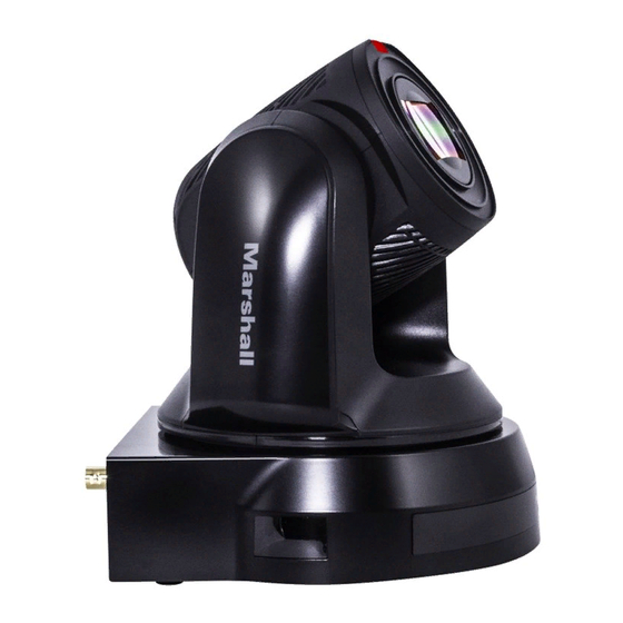
- Page 1 CV630-IP HD/UHD camera (PTZ Video Camera) User Manual - English...
-
Page 2: Table Of Contents
Table of Contents Copyright Information Chapter 1 Safety Instructions Chapter 2 Package Contents Chapter 3 Function Introduction I/O functions Introduction Description of LED indicator Tally Indicator Light Function Description Chapter 4 Instruction for installation Preparation before installation Instruction for installation Connecting devices Chapter 5 Remote Control and Setting Menu... -
Page 3: Copyright Information
Marshall Electronics, Inc., unless copying this file is for the purpose of backup after purchasing this product. In order to keep improving the product, Marshall Electronics, Inc. hereby reserves the right to make changes to product specifications without prior notice. The information in this file is subject to change without prior notice. -
Page 4: Chapter 1 Safety Instructions
Chapter 1 Safety Instructions Always follow these safety instructions when using the product: 1 Operation 1.1 Please use the product in the recommended operating environment. 1.2 Do not place the product in tilted position. 1.3 Do not place the product on an unstable trolley, stand or table. 1.4 Do not use this product near water or source of heat. - Page 5 Precautions ■ Warning: To reduce the risk of fire or electric shock, do not expose this appliance to rain or moisture. If Camera will not be used for an extended time, unplug it from the power socket. Caution: To reduce the risk of electric shock, do not remove cover (or back). No user-serviceable parts inside.
-
Page 6: Chapter 2 Package Contents
Chapter 2 Package Contents CV630-IP Remote Control Power Cord Power Adapter RS-422 Connector Appearance may vary depending on country/region Metal Plate A Metal Plate B M3 Screws Silver x8 / Black x2 English - 5... -
Page 7: Chapter 3 Function Introduction
Chapter 3 Function Introduction 3.1 I/O functions Introduction Item Function Descriptions Tally indicator light Displays the tally light status of the camera Camera lens 30x HD/UHD camera lens Power LED indicator Displays the status of the camera Standby LED indicator Displays the status of the camera RS-232 input port, up to 7 cameras can be connected in a RS-232 input... -
Page 8: Description Of Led Indicator
3.2 Description of LED indicator Status Power Standby Startup in progress Green light Orange light (initialization) In use Green light No indicator In standby mode No indicator Orange light 3.3 Tally Indicator Light Function Description 3.3.1 The tally indicator light function may be enabled through the control of RS-232 command. -
Page 9: Chapter 4 Instruction For Installation
Chapter 4 Instruction for installation 4.1 Preparation before installation Installation and setup of CV630-IP cameras requires special skills. To install by yourself, please follow necessary steps, ensure steady and secure mounting of the device, and pay attention to your safety to avoid any accidents, drops, or damage. - Page 10 4.2.2.2 Camera Size L x W x H : 174 x 186.1 x 189.7 mm Weight: 2.0 Kg 4.2.2.3 Max. rotation dimension of camera English - 9...
- Page 11 4.2.2.4 Size Diagram Bottom of camera base The camera can be mounted on a 1/4”, -20 UNC PTZ tripod deck by using the lock holes on the bottom for the tripod English - 10...
- Page 12 Metal Plate size diagram Metal plate B - ceiling side ■ English - 11...
- Page 13 Metal plate A – camera base side ■ English - 12...
- Page 14 4.2.2.5 Precautions for installation 1. Prior to installation, please confirm the orientation of the camera relative to the object to be captured to ensure Horizontal and Vertical integrity axis. 2. It is recommended for camera be set at a distance of one (1) meter or more from the object to be captured.
- Page 15 4. Combine the metal plate A and the metal plate B (1) Push the metal plate A up to the ceiling and then to the right to latch the metal plate B into place. (2) And then secure with 2 x M3 silver screws and 1 x M3 black screw 4.2.2.7 How to remove 1.
-
Page 16: Connecting Devices
4.3 Connecting devices 4.3.1 Connecting to PC (video conference) 3G/HD-SDI supports the audio output of 48 KHz only 4.3.2 Connecting to an HDTV/computer monitor via HDMI English - 15... - Page 17 4.3.3 Connecting to Internet For details of web page setup and description, please refer to Chapter 6 Network Function Settings Description 4.3.4 Connecting AUDIO IN Set the [Audio In] in the OSD to reflect the input device (mic or line level) English - 16...
- Page 18 4.3.5 Connecting RS-232 Up to 7 Marshall PTZ cameras can be connected with RS232 daisy chain ■ RS-232 pins definition instructions English - 17...
- Page 19 4.3.6 Connecting RS-422 Up to 7 Marshall cameras can be connected via RS422 daisy chain method. When RS-422 connection is being used, keep RS-232 connections vacant. ■ RS-422 pins definition instructions English - 18...
- Page 20 ■ RS-422 connection instructions 1. Hold the two sides of RS-422 connector and pull out in the direction shown by the arrow in the figure below 2. Peel off a section of copper wire (AWG Nos. 28 to 18) and insert it into the connector hole;...
-
Page 21: Chapter 5 Remote Control And Setting Menu
Chapter 5 Remote Control and Setting Menu 5.1 Functions of remote control <Remark> The below functions are listed alphabetically. Item Description Move the lens ,,, Back Light Turn on/off back light compensation Camera select Choose Camera ID 1 ~ 3 Focus- Turn on manual focus to adjust the focal Manual /... -
Page 22: Setting Menu
5.2 Setting Menu <Remark> Press [Menu] on the remote control to enter the setting menu; the bold underlined values in the following table are defaults. 1st Level 2nd Level 3rd Level Function Descriptions Major Items Minor Items Adjustment Values 1. Full Auto 2. - Page 23 3. F2.2 Iris Pri 4. F2.7 5. F3.2 6. F3.8 7. F4.5 8. F5.4 9. F6.3 10. F7.8 11. F9 12. F11 13. F13 14. F16 15. F18 16. Close 1. 0 dB 2. 3 dB 3. 6 dB 4. 9 dB 5.
- Page 24 1/30 1/25 1/15 1/12 1. F1.6 2. F2 3. F2.2 4. F2.7 5. F3.2 6. F3.8 7. F4.5 8. F5.4 Manual Iris Manually set the iris 9. F6.3 10. F7.8 11. F9 12. F11 13. F13 14. F16 15. F18 16.
- Page 25 5. ATW 3. 5800k 6. Manual 4. 1700k ~ 10000k 7. Sodium Lamp 5. 1700k ~ 10000k 6. Custom 7. 2800k One Push ENTER One push trigger Trigger Adjustable when the white Manual Red 0 ~ C ~ 128 balance mode is set to Manual Adjustable when the white Manual Blue...
- Page 26 Tilt Down Limit -30 ~ 0 Limit the downward angle Activate the reverse Pan Pan Flip On / Off command Activate the reverse Tilt Tilt Flip On / Off command 5 deg/sec 25 deg/sec 50 deg/sec Set the rotation speed of the 80 deg/sec Preset Speed cradle head when Preset is...
- Page 27 right keys or the numeric keys. Press [ENTER] to be in modify mode; select the item to be modified using the up Gateway 192.168.100.254 and down keys, and modify the value using the left and right keys or the numeric keys.
- Page 28 1. 3840 x 2160/29.97p 2. 3840 x 2160/25p 3. 1080p/59.94 4. 1080p/50 Output Mode 5. 1080p/29.97 Choose the output resolution 6. 1080p/25 7. 720p/59.94 8. 720p/50 9. 720p/29.97 10. 720p/25 Resume the factory default Factory Reset On / Off setting Display the current setting Status status...
-
Page 29: Chapter 6 Network Function Settings Description
2. To connect directly through network cable, the IP address of the computer should be changed so that it is on the same network segment as the camera e.g.: The factory-preset default IP address of CV630-IP is 192.168.100.100. The computer IP address must be set with the same network segment, such as 192.168.100.101, so that the computer can be connected correctly with the camera... - Page 30 6.1.2 Using the Browser to View the Images ■ Open the browser, and enter the URL of CV630-IP in the IP address bar e.g.: http://192.168.100.100 (default IP address) ■ Enter administrator’s account and password Marshall IP Camera I Account: admin I Password: 9999 6.1.3 Using Marshall VMS Software to View the Images...
-
Page 31: Web Page Function Description
6.2 Web Page Function Description 6.2.1 Login Screen Item Function Descriptions Username Enter user account (default: admin) Password Enter user password (default: 9999) Currently, the system supports English, Traditional Chinese and Language selection Simplified Chinese Save user account name and password to the browser. When you log Remember password in next time, there is no need to re-enter them Login... - Page 32 6.2.2 Viewing In Real Time Item Function Descriptions Pan / Tilt setting Adjust the Pan/Tilt position of the camera screen Zoom ratio Adjust the zoom-in or zoom-out ratio via scroll bar Preview window Display the screen currently captured by the camera Preset setting Select the number first and then select SAVE or LOAD Power button...
- Page 33 Set the new account management permissions Admin Operator Viewer User Type View images Settings Permission setting Account management Applying setting Add the newly created user to the list of account Edit: Modify the user password and permissions List of accounts Delete: Delete the user account 6.2.4 Setting-System Setting Item...
- Page 34 ■ Please use a camera name by mixing uppercase and lowercase letters or numbers. Do not use “/” and “space” or special symbols Streaming 1/ CV630-IP supports 3 streaming outputs. Please refer to 6.2.5.1 Streaming 2/ Streaming Parameter Setting for relevant settings...
- Page 35 6.2.6 Setting - Camera Item Function Descriptions Adjust the zoom-in or zoom-out ratio via scroll bar Zoom ratio Mode: Select exposure mode (Automatic/Shutter Priority/Aperture ■ Priority/Manual) Exposure Comp. Level: Select exposure compensation level ■ Gain: The gain limit is adjustable when the exposure mode is set to ■...
- Page 36 Mirror: Set automatic flip mode Mirror ■ Setting - Picture 6.2.7 Item Function Descriptions Picture Effect Set picture effect, Off/Neg/Black and White 2D noise reduction 2D noise reduction settings settings 3D noise reduction 3D noise reduction settings settings Image mode The user may customize his/her desired image mode When no custom setting is needed, reset the picture parameters back Image Mode Load...
- Page 37 6.2.8 Setting - Audio Item Function Descriptions Open audio Turn on/off sound Soundtrack effect Set MIC In/Line In setting Volume Adjust Volume Set Encode sample rate ⮚ 48 KHz (AAC) ⮚ Encode sample rate 44.1 KHz (AAC) ⮚ 16 KHz (G.711) ⮚...
- Page 38 6.2.9 Setting - Network Item Function Descriptions Network setting of camera. Change of setting is available when DHCP Network function is closed. Copy the RTMP web address provided by the RTMP service platform and paste it to the RTMP connection address to publish the camera images on the RTMP service platform RTMP Setting To upload to YouTube for live streaming, the audio function must be...
- Page 39 6.2.10 Setting-Time Item Function Descriptions Camera Time Display the date and time of the camera ■ Manually: Set time manually ■ Synchronize with computer time: Set the camera time according to the computer time Set the Time ■ Synchronize with SNTP server: Set the camera time synchronously with the SNTP server <Remark>...
- Page 40 Item Function Descriptions Event Logs If the camera encounters errors, an error code log will be established 6.2.13 Setting - Maintenance - System Service Item Function Descriptions Reset to the default Select the reset button to resume the factory default setting as the web value page setting The web page setting parameters can be exported from the computer...
- Page 41 About 6.2.14 Item Function Descriptions Camera name Display the camera name Firmware Version Display the firmware version of the camera Serial No. Display the camera serial No. English - 40...
-
Page 42: Chapter 7 Dip Switch Setting
Chapter 7 DIP Switch Setting 7.1 DIP SWITCH 7.1.1 OUTPUT Switch To switch via the OSD/ RS-232 Command is also available based on the last executed action Resolution Frame Rate 29.97 3840 x 2160 59.94 1920 x 1080 29.97 59.94 1280 x 720 29.97 Reserved... -
Page 43: Chapter 8 Troubleshooting
Chapter 8 Troubleshooting This chapter describes problems you may encounter while using CV630-IP. If you have questions, please refer to related chapters and follow all the suggested solutions. If the problem still occurred, please contact your distributor or Marshall IP technical support.
Need help?
Do you have a question about the CV630-IP and is the answer not in the manual?
Questions and answers