Advertisement
Quick Links
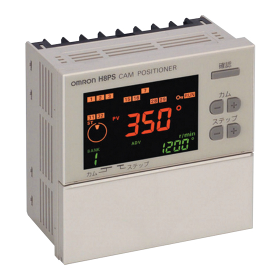
Cam Positioner
H8PS
This Compact Cam Positioner, Popular for Its
Ease-of-use, Now Comes with Even Better
Functions.
• Compact 8-, 16-, and 32-output Models available that are 1/4-
DIN size at 96 x 96 mm.
• High-speed operation at 1,600 r/min and high-precision settings
to 0.5° ensure widespread application.
• Highly visible display with backlit negative transmissive LCD.
• Advance angle compensation function to compensate for output
delays.
• Bank function for multi-product production (8 banks).
(H8PS-16@/-32@ models.)
• Speed display and pulse output.
• Approved standards: UL/CSA and EMC.
Features
Models with 8, 16, or 32 Outputs
The lineup includes Models with 32 outputs in a compact 1/4-DIN
size. Using the optional Parallel Input Adapter (Y92C-30) enables
expanding to up to 64 outputs for one encoder to support anything
from a simple positioning application to a large-scale system.
8-output Models
16-output Models 32-output Models
96 mm
96 mm
Simple Programming
The programming method is designed based on a one key-one
action concept for settings that could not be simpler. Both initial
settings and factory adjustments are effort-free.
Large, Backlit Negative LCDs
Large LCDs, red for the process value and green for set values, show
a wealth of operation information, making operating status visible at
a glance.
High Speed Up To 1,600 r/min
High Precision Up To 0.5° (at 720 Resolution)
High-speed, high-precision applications can be easily handled and
productivity increased.
Bank Function for Multi-product Production
Up to eight different programs can be registered in advance to
enable fast and easy switching between products (16/32-output
Models only).
USB Communications for Easy Setting from
a Computer
Optional Support Software can be used to enable programming from
a personal computer via USB communications. Programs can be
easily copied, saved, printed, and much more.
Refer to Safety Precautions for All Counters and
Safety Precautions on page 18 and 19.
Speed Display and Speed Alarm Output
Both the speed (rotations/minutes) and present angular position can
be displayed at the same time. Alarm outputs can be produced for
both upper and lower speed limits.
1
2
7
RUN
Present angular
position
Speed
Upper limit
STEP
CAM
Lower limit
Switchable
Upper limit
alarm output
1
2
7
Lower limit
RUN
alarm output
Speed
Present angular
position
CAM
STEP
Advance Angle Compensation Function to
Compensate for Output Delays
The advance angle compensation (ADV) function automatically
advances the ON/OFF angle of outputs in proportion to machine
(encoder) speed to compensate for the delay in timing of ON/OFF
operation. ADV values can be set individually for 7 cam outputs.
Cam program settings
At high-speed (400 r/min)
Pulse Output for Timing Control
The number of pulses per rotation and the pulse output start angle
can be set to enable operations like adjusting timing with a PLC or
outputting to a rotation meter.
Pulse output
CSM_H8PS_DS_E_6_2
Speed
100°
180°
°
8
compensation
92°
172°
PLC
Rotation meter
1
Advertisement


Need help?
Do you have a question about the H8PS-8AF and is the answer not in the manual?
Questions and answers