Advertisement
Quick Links
Connection manual of XDesignerPlus external devices
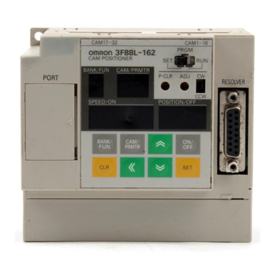
OMRON Industrial Automation
Cam Positioner Series
Support version
OS
XDesignerPlus
CONTENTS
Thank you for using "Touch Operation Panel (M2I TOP) Series" "of M2I Co. head
office. Please read this manual, and be familiar with the ways and procedures of
connecting the "TOP-external devices".
Explains the necessary appliances, setting of each appliances, cables,
available systems to access.
Select the suitable system referring to this article.
Explains an example of settings for communication interface between the
devices and the relevant external terminal.
Select an example according to the system you chose in "1. System
configuration".
4. Details of communication settings
Explains the way of setting TOP communication.
If external settings is changed, make sure to have the identical settings of
TOP with the external device referring to this chapter.
Explains cable specifications required for access.
Select proper cable specifications according to the system you chose in "1.
System configuration".
Check available addresses to communicate with external devices referring
to this chapter.
3F88L-160/162
Over V4.0
Over 4.0.0.0
Page 2
Page 3
Page 4
Page 5
Page 8
Page 9
1 / 12
Advertisement

Related Manuals for Omron 3F88L-160


Summary of Contents for Omron 3F88L-160
-
Page 1: Table Of Contents
OMRON Industrial Automation Cam Positioner Series 3F88L-160/162 Support version Over V4.0 XDesignerPlus Over 4.0.0.0 CONTENTS Thank you for using "Touch Operation Panel (M2I TOP) Series" "of M2I Co. head office. Please read this manual, and be familiar with the ways and procedures of connecting the "TOP-external devices". -
Page 2: System Configuration
1. Selecting TOP model and external devices System configuration of TOP and " OMRON Corporation – CAM Positioner Series 3F88L-160/162" "is as follows. Communicati Series Link I/F Systemsettings Cable on method 3.1 Example of 5.1 Cable table Communication Port CAM Positioner... -
Page 3: Select A Top Model And External Devices
Select “OMRON Industrial Automation”. Select the model series of external devices to be connected to TOP. External device Select “CAM Positioner Series 3F88L-160/162”. Please check, in the “1. System configuration”, if the relevant external device is available to set a system configuration.. -
Page 4: Example Of System Settings
– On the right window, [ HMI Setup > HMI Setup use check > Device manager ] ■ External device settings Set options of communication driver for “CAM Positioner Series 3F88L-160/162”.. – PLC station number(PLC): The station number same as external devices... - Page 5 (2) External device settings Set the function parameters of the external devices as shown below. Please refer to the User's Manual of external devices for more detailed settings. 1. Set “Function No. b, Parameter No. 6” as “1”. Set the Parity bit 9600 bps(factory setting) Switch the power of the external device “off”...
- Page 6 – On the right window, [ HMI Setup > HMI Setup use check > Device manager ] – On the right window, [ HMI Setup > HMI Setup use check > PLC Setup] ■ External device settings Set options of communication driver for "CAM Positioner Series 3F88L-160/162". ■ Communication interface settings Details Contents Select a serial communication method between TOP –...
- Page 7 4.2 Setting details of TOP main menu - When hearing the sound while resetting the power, touch 1 upper point on LCD to move to“TOP management main” screen.. - Set the driver interface settings of TOP according to the contents; Step1 → Step2. (You can change the settings in Step2.if you click on “TOP COM 2/1 settings”...
- Page 8 4.3 Communication check ■ Check the interface settings between external devices - TOP. - Resetting the power of TOP, move to the menu screen by clicking on the top of the LCD window. - Check that the settings of the port [COM 2 or COM 1] to use in [Communication settings] are the same with the settings of external devices.
-
Page 9: Cable Table
5. Cable table This Chapter introduces the cable diagram for normal communication between TOP and the relevant devices. (The cable diagram explained in this chapter can be different from the recommended details of “OMRON Industrial Automation”) 5.1 Cable table 1 ■... -
Page 10: Support Address
6. Support address The device which is available at TOP is as follows. There can be a device range difference according to the module series/type of CPU. Refer to the user's manual of each CPU module. Be careful not to be out of the address range that the relevant device supports - Memory Area Read (RUN) : M Address Name... - Page 11 Address Name Detailed information 32 BIT available Bank2 Same as for bank1 0020 Address 0020 to 0023 : Bank 2 cam data protect setting Address 0024 to 0027 : Bank 2 one-direction function setting 002B Address 0028 to 002B : Bank 2 rotation direction setting Bank3 Same as for bank1 0030...
- Page 12 Address Name Detailed information 32 BIT available 6000 Programs for Bank 6 Same as for Bank 1 6BCF 7000 Programs for Bank 7 Same as for Bank 1 7BCF 8000 Programs for Bank 8 Same as for Bank 1 8BCF *Note1)The 8 digits of data can be read when the P0000 address uses 32BIT.
Need help?
Do you have a question about the 3F88L-160 and is the answer not in the manual?
Questions and answers