
Related Manuals for Atlanta Attachment Company 1393E


Summary of Contents for Atlanta Attachment Company 1393E
- Page 1 1393E model Revision 2 Updated Oct.8, 2015 Technical Manual & Parts Lists Atlanta Attachment Company 362 Industrial Park Drive Lawrenceville, GA 30046 770-963-7369 • www.atlatt.com...
- Page 3 Attachment Company. In addition to any confidentiality and non-disclosure obligations that currently exist between you and Atlanta Attachment Company, your use of these materials serves as an acknowledgment of the confidential and proprietary nature of these materials and your duty not to make any unauthorized use or disclosure of these materials.
-
Page 4: Table Of Contents
Technical Manual & Parts Lists Contents Important Safety Instruction ........................1 Liability ..............................2 Safety Equipment on the Machines ......................3 Protective Eyewear ............................. 4 Important Notices............................5 Maintenance ..............................7 Repair ................................8 A Word to the End User..........................9 Safety Precautions ............................ - Page 5 Monthly ..............................44 3.- SERVICE MANUAL .......................... 45 1.- Pneumatic ............................45 1393E Panel Cutter Spare Parts Kit ......................46 XCut Drive Motor Parameters Menu (INV1) ................... 48 Infeed Drive Motor Parameters Menu (INV2) ..................51 Assembly Drawings & Parts Lists ......................55...
-
Page 6: Important Safety Instruction
Mandatory Information All persons operating and/or working on the 1393E Autopack should read and understand all parts of the Safety Instructions. This applies, in particular, for persons who only operate and/or work on the unit occasionally (e.g. for maintenance and repair). Persons who have difficulty reading must receive particularly thorough instruction. -
Page 7: Liability
Technical Manual & Parts Lists Liability The machine should only be operated when in perfect working order, with due regard for safety and the potential dangers, as well as in accordance with the Instruction Material. Faults and malfunctions capable of impairing safety should be remedied immediately. We cannot accept any liability for personal injury or property damage due to operator errors or non-compliance with the safety instructions contained in this booklet. -
Page 8: Safety Equipment On The Machines
A Word to the Operator The greatest danger inherent in our machines: is that of fingers, hands or loose clothing being drawn into a machine by live, coasting or rotating tools or assemblies or of being cut by sharp tools or burned by hot elements. LWAYS BE CONSCIOUS OF THESE DANGERS Safety Equipment on the Machines All machines are delivered with safety equipment, which shall not be removed or... -
Page 9: Protective Eyewear
Technical Manual & Parts Lists Protective Eyewear Protective eyewear that has been tested by the local authorities should be worn whenever there is a possibility of loose or flying objects or particles such as when cleaning the machine with compressed air. Tools Always count the number of tools in your possession before starting work on the machine. -
Page 10: Important Notices
Important Notices Reporting and Fighting Fires Read the instructions posted in the factory with regard to reporting fires and the emergency exits. Make sure you know exactly where the fire extinguishers and sprinkler systems are located and how they are operated. - Page 11 Technical Manual & Parts Lists - Kinetic energy - Note that some motors or spindles, for example, may continue to run or coast run on after being switched off. - Potential energy - Individual assemblies may need to be secured if necessary for repair work. Delivery of the Machine/Packaging Note any markings on the packaging, such as weights, lifting points and special information.
-
Page 12: Maintenance
Protect against influences from the surroundings: no structure-borne vibrations, no grinding dust, or chemical vapors. Protect against unauthorized access. Ensure that the machine and accessories are set up in a stable position. Ensure easy access for operation and maintenance (Instruction Manual and layout diagram); also verify that the floor is strong enough to carry the weight of the machine. -
Page 13: Repair
Technical Manual & Parts Lists Repair Replacement Parts We cannot accept any liability whatsoever for damage due to the use of parts made by other manufacturers or due to unqualified repair or modification of the machine. Repair, Electrical The power supply must be switched off (master switch off) and secured so that it cannot be switched on again inadvertently before starting any work on live parts. -
Page 14: A Word To The End User
A Word to the End User The end user has sole responsibility to enforce the use of safety procedures and guards on the machine. Any other safety devices or procedures due to local regulations should be should be retrofitted in accordance to these regulations and/or the EC Directive on the safety of machines. -
Page 15: Installation Manual
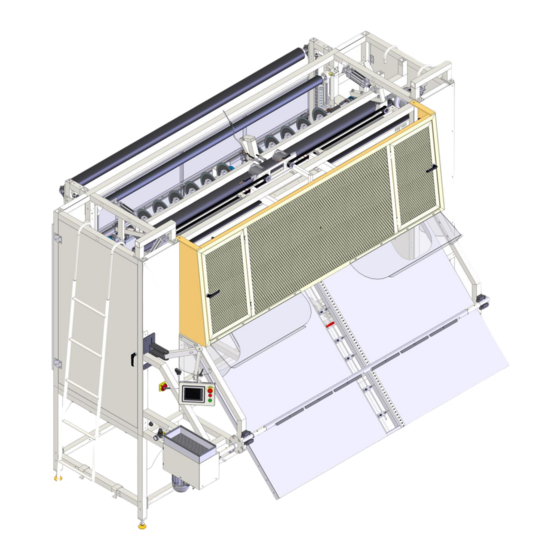
Technical Manual & Parts Lists 1.- INSTALLATION MANUAL It is important that the machine operator read this manual and is familiar with all the functions and safety concerns of the unit before operating. 1.1.- Parts and Components (12) (10) (11) 1.- Main Power 5.- Right Edge cut 9.- Width Sensors... -
Page 16: Technical Data
1.2.- Technical Data Foot Print... -
Page 17: Installation & Set Up
Technical Manual & Parts Lists 1.3.- Installation & Set Up It is important that the machine operator read this manual and is familiar with all the functions and safety concerns of the unit before operating 1.- Unpack the machine frame and install it with help of crane and forklift. 2.- Remove any shipping straps from machine. -
Page 18: Operation Manual
2.- OPERATION MANUAL It is important that the machine operator read this manual and is familiar with all the functions and safety concerns of the unit before operating 2.1 Individual components a.- Main Power It is located below the touch screen panel. Is the main power switch ¼... -
Page 19: D.- Table Lift Operation
Technical Manual & Parts Lists d.- Table Lift Operation. This allows the operator to select the position of the out-feed table. If “Table Lift Up” is selected, the table will lift and lock in place for cutting panels. If “Table Lift Down” is selected, the table will lower to allow the windup roller to be used to wind up material. -
Page 20: Touch Screen
2.2.- Touch Screen Main Menu This menu is displayed at the startup of the machine. Press any of the frames in the screen and you will be transfer to the following sub-menu PANEL MODE BORDER MODE MANUAL MODE ... -
Page 21: Edge Blade Setup & Adjustment Procedure
Technical Manual & Parts Lists 2.2.1 Edge Blade Setup & Adjustment Procedure 1) Set the center distance between the LEFT and RIGHT edge trim blade home position proximity switches to 90.5” (2300mm) 2) On the touchscreen menu………Select Blade Position. Set a Left Offset value to 5.00” (127mm) and Cut Length value to 85.00”... - Page 22 4) Assuming Step 3 was completed correctly, measure the center distance (blade to blade) between the blades. It should measure 90.5” (2300mm). 5) If the distance between the blades is not 90.5” (2300mm) recheck the center distance between the home left and right home position proximity switches. Move the proximity target / flag on each edge trim blade in the direction needed to get 90.5”...
-
Page 23: A.- Panel Cut Mode
Technical Manual & Parts Lists a.- Panel Cut Mode cuchCC6.1.2... - Page 24 Starting at Main Menu Select PANEL CUT MODE from the Main Menu screen You will get a NOTE Screen Manually change the position of the Selector to PANEL Press CONTINUE TO PANEL MODE PANEL CUTTING MENU: 1.- PANEL QUANTITY REQUIRED Enter the number of panels to cut.
- Page 25 Technical Manual & Parts Lists 2.- PANEL QUANTITY PRODUCED The number of panels ALREADY produced since that number was last cleared. After selecting a number field a number pad will come up. Enter the desired number and select ENT to enter that number in the desired location. 3.
- Page 26 Location of the sensors on the panel table. After pressing the blank space you will get the 6. PANEL CUT LENGTH screen This screen is divided in 3 main columns. STANDARD for normal thickness. PLUSH for thick panels. ...
- Page 27 Technical Manual & Parts Lists 6.1.1- To change dimensions, press on top of the number and modify the values 6.1.2- EDIT PLUSH SETTINGS to change the rest of the sizes. 6.1.3- EDIT PILLOW TOP SETTINGS to change the rest of the sizes. 6.14.- RETURN TO CUT LENGTH MENU to exit the screen 6.2 CANCEL SIZE CHANGE return to the original values.
-
Page 28: B.- Border Cut Mode
b.- Border Cut Mode... - Page 29 Technical Manual & Parts Lists Starting at Main Menu Select BORDER CUT MODE from the Main Menu screen You will get a NOTE Screen Manually change the position of the Selector to BORDER Press CONTINUE TO BORDER MODE After pressing BORDER CUT MODE from the MAIN MENU you will arrive to the BORDER CUTTING MENU...
- Page 30 2.- BORDER QUANTITY PRODUCED This is the number of preselected border lengths produced since this value was last cleared. After selecting a number field a number pad will come up. Enter the desired number and select ENT to enter that number in the desired location. 3- TOTAL BORDER OUTPUT This is the total number of border lengths produced since this value was last cleared.
- Page 31 Technical Manual & Parts Lists 5- BORDER CUT LENGTH This is to set the length of border to be produced. When this length is reached the border will be cross cut. The units are in inches. After selecting a number field a number pad will come up.
-
Page 32: C- Position Trim Blades
c- Position Trim Blades... - Page 33 Technical Manual & Parts Lists Starting at Main Menu Press POSITION TRIM BLADES you will get the BLADE POSITION MENU screen. 1.- RIGHT POSITION OFFSET This sets the distance from the right side (near the touch screen) that the trim knife will be set. After selecting a number field a number pad will come up.
- Page 34 3.- SIZE SELECT. This is useful to select a preset cut setting for a desired panel length. 4.- CUT WIDTH Show the value of the actual cut width according to the width sensor selected. 5.- CUT SENSOR Press Letter and size will be highlighted 6.- POSITION TRIM BLADES When the desired changes have been entered move the “Position/Off”...
-
Page 35: D- Maintenance Menu
Technical Manual & Parts Lists d- Maintenance Menu... - Page 36 Starting at Main Menu Press MAINT. MENU you will get the MAINTENANCE MENU P1 screen. 1.- IN-FEED JOG FORWARD The main rollers will turn in the direction to advance material. 2.- IN-FEED JOG REVERSE The main rollers will turn in the direction to reverse the material 3.- X-CUT CLAMP UP The crosscut clamp bar will rise.
- Page 37 Technical Manual & Parts Lists 14.1 - PLC INPUTS 14.2 – PLC OUPUTS...
- Page 38 15- MAINT MENU PAGE 2 15.1-ROTATE SIDE TRIM BLADES 15.2-ROTATE SLITTER BLADES 15.3-ROTATE X-CUT BLADES FORWARD 15.4-ROTATE X-CUT BLADES REVERSE 15.5-MOVE TRIM BLADES LEFT 15.6-MOVE TRIM BLADES RIGHT 15.7-MOVE X-CUT BLADE LEFT 15.8-MOVE X-CUT BLADE RIGHT 15.9-IO MONITOR 16.0-TIMER SETTING MENU 16.1-MAINT.
-
Page 39: E- Panel Cut Batch
Technical Manual & Parts Lists e- Panel Cut Batch 1- NUMBER FIELDS 2- BATCH DATA MENU... - Page 40 2.1 VIEW DATA MENU 3.- CROP-OUT CUT MENU 4.- CUT SIZE ADJUST MENU 5.- MAIN MENU 6.- RUN 7.- WITH : LENGTH : PRODUCE 8.- STOP...
- Page 41 Technical Manual & Parts Lists f.- Manual Mode...
- Page 42 1.- MANUAL FEED FORWARD WITH SIDE TRIM Will advance material while side trimming. 2.- MANUAL FEED MATERIAL REVERSE Will reverse material with side trim knives not running. 3.- MANUAL FEED MATERIAL FORWARD Will advance material without side trimming. 4.- JOG BORDER WINDER The border winder motor will turn.
-
Page 43: G.- Select Cut Length
Technical Manual & Parts Lists g.- Select Cut length This screen is divided in 3 main columns. STANDARD for normal thickness PLUSH for thick panels PILLOW TOP for extra thick The highlighted fields are the ones active as this time 1.- CHANGE CUT SIZE SETTINGS after pressing this field the screen... -
Page 44: H.- Sharpen Blades
h.- Sharpen Blades 1.- SHARPEN LEFT BLADE – This will turn on the left trim knife motor and activate the sharpener for the predetermined time. 2.- SHARPEN RIGHT BLADE – This will turn on the right trim knife motor and activate the sharpener for the predetermined time. -
Page 45: I.- Timer Settings Menu
Technical Manual & Parts Lists i.- Timer settings menu 1.- LUBE INTERVAL Control the activation trimming automatic grease system. (OPTIONAL EQUIP.) 2.- SHARPENER RUN TIME 3.- OUT FEED RUN TIME 4.- SET SYSTEM CLOCK Press any of the field and change values on the Keypad. -
Page 46: J.- Control Power Start
j.- Control Power Start Press this button to energize the control power to the machine k.- POWER OFF / POWER ON This is an indicator to show when the control power is energized (Not a Button) l.- Control power off Press this button to de-energize all the control power to the machine. -
Page 47: Operating
Technical Manual & Parts Lists 2.3.- Operating It is important that the machine operator read this manual and is familiar with all the functions and safety concerns of the unit before operating A.- Turning ON a.- Make Sure that the Main Power switch is on the “ON”... -
Page 48: C.- Panel Cutting
d.- close the safety doors and press CLOSE IN FEED ROLLER from the loading menu. e.- Press PREV MENU to Return to the Main menu c.- Panel Cutting a.- Set the table Lift switch to “Up” and remove the re-winder shaft b.- Make sure machine is loaded with material and all doors are close c.- Press CONTROL POWER START from the... -
Page 49: Maintenance
Technical Manual & Parts Lists 2.4.- Maintenance a.- Daily 1.- Drain water from water trap in air pressure regulator. 2.- Clean any lint or debris from around bearings, blades and motors. 3.- Clean work area and check for any signs of abnormality or wear. -
Page 50: Service Manual
3.- SERVICE MANUAL It is important that the machine operator read this manual and is familiar with all the functions and safety concerns of the unit before operating. 1.- Pneumatic a.- Re-winder pressure. Control the pressure of the clutch Determine how tight the roll will be winder. -
Page 51: 1393E Panel Cutter Spare Parts Kit
Technical Manual & Parts Lists 1393E Panel Cutter Spare Parts Kit QTY PART # DESCRIPTION 1393003 SHARPENER STONE MNT AAE4V21008 VALVE,1/4" PORTED,24VDC BBGER205-25 BEARING,BALL,25MM B,CLAMP CJ2090200 BLADE, TRIM & XCUT,280MM OD CJ21100900 BLADE, SLITTER, 205MM OD EEMC12B11 CONTACTOR,IEC,230VAC EEMC32A22 CONTACTOR,IEC,230VAC... - Page 52 Programming ACTech SCL/SCM Drive (1393E Only) The drive is already pre-programmed** with settings specifically for the 1393E Unit by Atlanta Attachment Co. These settings are listed in the chart on the following page. Password protection is currently disabled so that control of the parameters is immediately available to the user.
-
Page 53: Xcut Drive Motor Parameters Menu (Inv1)
Technical Manual & Parts Lists XCut Drive Motor Parameters Menu (INV1) AAC custom setting shown in last column. PARAMETER NAME RANGE OF ADJUSTMENT FACTORY DEFAULT SETTING LINE VOLTAGE High (01), LOW (02) HIGH (01) CARRIER 4kHz (01), 6kHz (02), 8 kHz (03), 10 kHZ 6 kHZ (02) FREQUENCY (04) - Page 54 TERMINAL STRIP ONLY (01) TERMINAL CONTROL REMOTE KEYPAD ONLY (02) STRIP ONLY (01) UNITS EDITING TENTHS OF UNITS (01), WHOLE UNITS WHOLE (02) UNITS (02) ROTATION FORWARD ONLY (01), FORWARD FORWARD AND REVERSE (02) ONLY (01) ACCELERATION 0.1 - 3600.0 SEC 20.0 SEC TIME DECELERATION...
- Page 55 Technical Manual & Parts Lists USER SETTINGS (01), OEM SETTINGS SCL = RESET PROGRAM (02), RESET OEM (03), RESET 60 (04), 50 (05) SELECTION RESET 50 (05), TRANSLATE (06) SCM = RESET 60 (04) FAULT HISTORY (VIEW ONLY) (N/A) SOFTWARE CODE (VIEW ONLY) (N/A) DC BUS VOLTAGE...
-
Page 56: Infeed Drive Motor Parameters Menu (Inv2)
Infeed Drive Motor Parameters Menu (INV2) AAC custom setting shown in last column. PARAMETER NAME RANGE OF ADJUSTMENT FACTORY DEFAULT SETTING LINE VOLTAGE High (01), LOW (02) HIGH (01) CARRIER 4kHz (01), 6kHz (02), 8 kHz (03), 10 kHZ 6 kHZ (02) FREQUENCY (04) NORMAL (01), START ON POWER UP... - Page 57 Technical Manual & Parts Lists TERMINAL STRIP ONLY (01) TERMINAL CONTROL REMOTE KEYPAD ONLY (02) STRIP ONLY (01) UNITS EDITING TENTHS OF UNITS (01), WHOLE UNITS WHOLE (02) UNITS (02) ROTATION FORWARD ONLY (01), FORWARD FORWARD AND REVERSE (02) ONLY (01) ACCELERATION 0.1 - 3600.0 SEC 20.0 SEC...
- Page 58 USER SETTINGS (01), OEM SETTINGS SCL = RESET PROGRAM (02), RESET OEM (03), RESET 60 (04), 50 (05) SELECTION RESET 50 (05), TRANSLATE (06) SCM = RESET 60 (04) FAULT HISTORY (VIEW ONLY) (N/A) SOFTWARE CODE (VIEW ONLY) (N/A) DC BUS VOLTAGE (VIEW ONLY) (N/A) MOTOR VOLTAGE...
- Page 59 Technical Manual & Parts Lists...
-
Page 60: Assembly Drawings & Parts Lists
Company. In addition to any confidentiality and non-disclosure obligations that currently exist between you and Atlanta Attachment Company, your use of these materials serves as an acknowledgment of the confidential and proprietary nature of these materials and your duty not to make any unauthorized use or...
Need help?
Do you have a question about the 1393E and is the answer not in the manual?
Questions and answers