
Subscribe to Our Youtube Channel
Related Manuals for red lion BT-6821-AT-AC


Summary of Contents for red lion BT-6821-AT-AC
- Page 1 IndustrialPro™ and MobilityPro™ Gateway Wireless Modems User's Guide Version 1.15 August 15, 2014...
- Page 2 Red Lion and any of its subsidiaries or other affiliates shall not be liable for any damages (including, but not limited to, consequential, indirect or incidental, special damages, or loss of profits or data) even if they were foreseeable and Red Lion has been informed of their potential occurrence arising out of or in connection with this document or its use.
- Page 3 Federal Communication Commission Interference Statement This equipment has been tested and found to comply with the limits for a Class B digital device, pursuant to Part 15 of the FCC Rules. These limits are designed to provide reasonable protection against harmful interference in a residential installation. This equipment generates uses and can radiate radio frequency energy and, if not installed and used in accordance with the instructions, may cause harmful interference to radio communications.
- Page 4 Industry Canada This device complies with Industry Canada license-exempt RSS standard(s). Operation is subject to the following two conditions: (1) this device may not cause interference, and (2) this device must accept any interference, including interference that may cause undesired operation of the device. This radio transmitters BT-5630v2 / BT-5830v2 (IC: 2991A-BT5X30V2) and BT-5730v2 have been approved by Industry Canada to operate with the antenna types listed below with the maximum permissible gain and required antenna impedance for each antenna type indicated.
- Page 5 While every effort has been made to achieve technical accuracy, information in this document is subject to change without notice and does not represent a commitment on the part of Red Lion Controls, or any of its subsidies, affiliates, agents, licensors, or resellers. There are no warranties, express or implied, with respect to the content of this document.
- Page 6 Updated to cover BT-57xx LTE models 1.13 February 15, 2012 Updated to cover BT-5x30 Wi-Fi models Update event and store and forward sections 1.10 September 27, 2010 Update environmental specifications June 7, 2010 Add modem pictures Red Lion labels March 30, 2010 Change document format...
-
Page 7: Table Of Contents
Table of content Product Overview ............................. 10 1.1 Introduction ................................10 1.2 Modem features ..............................11 1.3 Specifications ................................13 BlueVue Device Manager (BVDM) ........................24 2.1 Connecting to the modem ............................25 2.2 Software overview ..............................27 AT Commands ..............................28 3.1 Access .................................. - Page 8 11.5 USB cable ................................51 11.6 Serial cable ................................51 11.7 Power source ............................... 51 Appendixes ..............................53 12.1 BlueVue Device Manager Troubleshooting ......................53 12.2 Activation Troubleshooting ..........................57 12.3 Troubleshooting ..............................60 12.4 Firmware Upgrades ............................. 63 12.5 Sending AT Commands ............................
- Page 9 Figures Figure 1 - Router mode ................................. 11 Figure 2 - IP pass-through mode ............................11 Figure 3 – Serial connector (looking at back of modem) ...................... 23 Figure 4 – The different ways to connect to a modem ......................25 Figure 5 –...
-
Page 10: Product Overview
1 Product Overview Introduction The BlueTree 5000v2 and 6000 series modems are rugged cellular modems built to provide simple and reliable communication over a CDMA or GSM cellular data networks. They are typically used in applications such as Public Safety, Transportation, Vehicle Tracking, Telemetry, SCADA, Remote / Temporary Offices, Landline Replacement, and WAN backup / Business Continuity. -
Page 11: Modem Features
Figure 1 - Router mode The modem manages two connections at the same time, thus acting as a gateway/router: Cellular WAN connection: This is the Wide Area Network connection to the cellular network/Internet. The modem can be configured to automatically and autonomously establish a packet data connection to the cellular carrier and acquire a WAN IP address. -
Page 12: Table 1 - Modem Features
Table 1 – Modem features 3 different data connection Serial/RS-232/COM, Ethernet, and USB interfaces Available on the BT-6x21 models only. These models have an embedded 5- Ethernet switch port Ethernet switch. Models ending in EB (BT-6x01EB) are models with built in power sourcing. Power-over-Ethernet Power-over-Ethernet compatible devices can be powered simply by connecting it to the modem’s Ethernet port. -
Page 13: Specifications
only). Sensors can be connected to the I/O ports of the modem. Depending on models, the modem is capable of monitoring up to four digital inputs for any change in state, and up to three analog inputs for changes in gradient data sources. - Page 14 Power consumption See Table 6 BT-5000v2 series Operating Temp: -40 to +85°C (-40 to 185°F) Shock & Vibration: MIL-STD 810F/202G Humidity: 5 to 95% non-condensing Environmental BT-6000 series Operating Temp: -40 to +85°C (-40 to 185°F) Shock & Vibration: IEC 60068-2-1/2/6/27/30, DNV 2.4 3.7/8/9, MIL-STD 810F/202G Humidity: 5 to 95% non-condensing Hazardous Locations - Class I, Div.
- Page 15 1.3.3 Mechanical specifications BT-6000...
-
Page 17: Table 3 - 4-Pin Molex Connector (Bt-5Xx0V2)
1.3.4 Power specifications and consumption Power is supplied to the modem via: 4-pin Molex connector for the BT-6x00 and BT-5x00v2 models 4-pin screw terminal for the BT-6x01, BT-6x01EB and BT-6x21 models DC 2.5mm barrel plug for all BT-6000 models ... -
Page 18: Table 5 - 4-Pin Screw Terminal (Bt-6Xx1)
1.3.4.3 4-pin Screw Terminal (BT-6xx1) Power is supplied to the modem via the 4-pin Screw Terminal on the front panel for the BT-6xx1 models. The pins are described as follows: Table 5 - 4-pin screw terminal (BT-6xx1) Name Description Ground PWR+ Power supply input (8 to 30 VDC) Digital output... - Page 19 All modems are equipped with protection for reversed polarity and power surges over 33 volts. The modems are equipped with an internal 3 Amp fuse. When using the 4 pin Molex connector / power accessory cable supplied by BlueTree Wireless, an extra 2 Amp fuse is also included (5600v2, 5800v2).
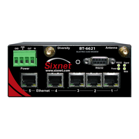
- Page 20 1.3.5 Modem views (Red Lion labels) BT-5600v2 BT-5800v2 Standalone GPS BT-5700v2 With Wi-Fi(5x30 only) BT-5730v2 BT-5630v2 BT-5830v2 BT-5xx0v2 BT-6600 4-pin power connector BT-6700 BT-6800 BT-6x00 BT-6401* BT-6601 Screw-block power connector ...
- Page 21 1.3.6 Modem views (BlueTree labels) BT-5600v2 Standalone GPS BT-5800v2 BT-5x00v2 BT-6600 4-pin power connector BT-6800 BT-6x00 BT-6401* Screw-block power connector BT-6601 BT-6801 BT-6x01 BT-6401EB* Screw-block power connector & BT-6601EB PoE power input BT-6801EB BT-6x01EB ...
-
Page 22: Table 8 - Leds
1.3.7 Indicators Lights (LED) Table 7 – LEDs Status Corresponding State Modem is powered off Power Modem is powered on FLASH Firmware error No signal available or signal strength is below -100 dBm Excellent signal strength = greater than -69 dBm Signal Fast: Every 300ms = -79 to -70 dBm FLASH... -
Page 23: Figure 3 - Serial Connector (Looking At Back Of Modem)
1.3.8.3 Serial Port (DB9) The modem’s serial port is an RS232 DCE, compliant with EIA-232 standard. The connector used is DB9 female and is shown in the illustration below. Figure 3 – Serial connector (looking at back of modem) For further serial wiring information, refer to the Hardware Installation section. -
Page 24: Bluevue Device Manager (Bvdm)
BlueVue Device Manager (BVDM) The BlueTree BT-5000v2 and BT-6000 series modems can be configured using BlueVue Device Manager version 1.76 or later. This software application is available as a free download at www.redlion.net. Later sections of this guide will refer to configuration options in this software. -
Page 25: Connecting To The Modem
Connecting to the modem Should you run into any issues connecting to the modem, refer to the BlueVue Device Manager Troubleshooting appendix. Click on Tools > Settings > Connection tab to select the interface your PC will use to connect to the modem. Figure 4 –... -
Page 26: Figure 5 - Connecting To A Remote Modem
The modem will be added to the list of Available Modems, which will be saved for easy access in the future. Double-click the modem name in order to connect to it. Figure 5 – Connecting to a remote modem... -
Page 27: Software Overview
Software overview Modem Diagnostic This screen displays various technical information pertaining to the modem's state. Modem Configuration This screen allows the user to configure the modem to suit the application requirements. Modem Activation This screen is where the user performs cellular account activation so that the modem may connect to the cellular network. -
Page 28: At Commands
AT Commands The BlueTree BT-5000v2 and BT-6000 series modems can be configured and managed using AT commands. AT is a command line interface allowing full control over the modem functionalities and diagnostics. The AT commands are described in the AT command reference document available from www.redlion.net. AT commands allow for the creation of configuration scripts used to configure a fleet of modems with the same settings. -
Page 29: Activation & Wan Setup
Activation & WAN Setup Activation (CDMA modems only) A modem must be activated and configured before it can be used on the cellular network. The steps below outline how to activate a modem. To configure the modem to connect to the wireless network after activation has been performed, skip to the next section. -
Page 30: Wan Setup
Figure 6 – Confirming the success of activation WAN Setup After the modem has been activated, it must be configured in order to authenticate for use with the cellular network. 4.2.1 Enter the account information Navigate to WAN (WAN Settings) to configure the WAN connection once the modem has been activated. -
Page 31: Figure 7 - Editing The Account Information
Figure 7 – Editing the account information Enter the Dial String: #777 for CDMA modems *99# for HSPA modems (Bell Mobility and Telus) *99***1# for other GSM modems (EDGE and HSPA) Enter the User Name and Password if provided by your cellular carrier otherwise, leave them empty. Select Always On or On Demand (explained below) depending on the desired connection initiation behavior. -
Page 32: Figure 8 - Testing The Connection
Figure 8 – Testing the connection... -
Page 33: Lan Setup
LAN Setup Ethernet and USB LAN Computers and devices that use the modem’s Ethernet and USB connectivity experience much higher transfer speeds and they employ all the benefits of TCP/IP communication. LAN configuration Whether an Ethernet or USB cable is used, it is essential that both the modem and the attached device be within the same LAN subnet for IP communication to take place. -
Page 34: Wireless(Wifi)
modem's IP lies in the same subnet as the device. Navigate to CONF (Modem Configuration) > LAN IP and change the parameters under Ethernet or USB. Figure 10 – Sample modem configuration for communicating with a device that has the IP 10.127.0.17 Wireless(WiFi) All configuration of the integrated Wi-Fi feature in the BT-5x30 is done via AT commands only. -
Page 35: Ip Networking Features
IP Networking Features As mentioned previously, the modem acquires an external public or private IP address (WAN IP, or Wide Area Network IP) from the cellular network upon establishing a connection. A remote user can communicate with the modem or a host behind the modem;... -
Page 36: Dmz
Figure 11 – Port-forwarding entries The WAN Port is the destination port number used by the remote computer and the LAN Port is where the data is forwarded to. Typically the WAN port and LAN port are the same; however any port can be used on the WAN side, as long as it points towards the correct LAN port. -
Page 37: Ip Pass-Through
DMZ is ideal in situations where there is already a server on the LAN that handles port-forwarding, as it avoids having to re-program all the port-forwarding rules into the modem. It is also practical when the user does not know which ports his local device listens on, and just wants everything to work with minimal configuration. -
Page 38: Dynamic Ip Registration
This mode allows only one IP address to be assigned to the first connected device via DHCP (This configuration is not recommended for BT-6x21). Dynamic IP registration This feature allows the modem to report a message to a user-configurable IP address every time its WAN IP address changes. -
Page 39: Access Control List (Acl)
IP Security can only be configured and managed via AT commands. Access Control List (ACL) The modem can be configured with Access Control List to prevent un-authorized incoming IP traffic. Please refer to the "Getting Started with ACL" application notes for further details. Note ACL cannot only be configured and managed via AT commands. - Page 40 Click Submit to save the changes.
-
Page 41: Serial Ip
Serial IP This feature allows communication over the cellular network in two common setups. The first is a server communicating with a remote serial-only device and the other, a serial-only device communicating with another remote serial-only device. Serial IP is used to emulate a direct serial connection to the attached device, or to emulate a landline modem. The modem becomes a transparent middleman routing data back and forth between the poller and the pollee. -
Page 42: Gps
The BT-5600v2 and BT-5800v2 modems have an embedded GPS receiver which can be used to track their movement. This feature is commonly used in applications such as asset-tracking and Automatic Vehicle Location (AVL). These modems support two GPS protocols: the National Marine Electronics Association (NMEA) protocol and the Trimble ASCII Interface Protocol (TAIP). -
Page 43: Gps Protocols
GPS protocols 8.1.1 TAIP TAIP is configured using a single command string. Read Trimble’s TAIP documentation to learn how to create a command that meets your needs. The modem listens on UDP port 21000 for TAIP commands, allowing its configuration to be modified on the fly by software applications that support TAIP. - Page 44 The first is to use BlueVue Device Manager for basic GPS reporting. This allows easy configuration of timer-based GPS reports. Refer to the Basic GPS Reporting in BlueVue Device Manager appendix for a step-by-step configuration example. The second is to use AT commands for advanced configuration. This method is more complex and can take advantage of the modem's Event Reporting capabilities (see next section).
-
Page 45: O Management
I/O Management BlueTree offers a complete set of AT commands to query or set its general purpose and dedicated input and output pins. This section is only meant to offer a basic outline of how the user can interact with the modem’s I/Os. The actual modem I/O depends on the model. -
Page 46: Analog Input Value Query
Analog Input value query The modem has a 10-bit Analog to Digital Converter (ADC) which allows it to monitor all of its general purpose analog input(s) for a change in state, along with the dedicated power input. The value of these inputs can be queried by sending the following command: AT+BAIGET? Sample response from modem (the actual output depends on the modem model):... -
Page 47: Event Reporting
Event Reporting Event Reporting is covered in its own document, the I/O Management & Event Reporting Guide. This section is meant to provide a general overview of what can be accomplished with the modem’s BlueTree Event Protocol engine. Event Reporting is used to program the modem to automatically perform an action (such as sending a report) whenever a user-defined event occurs. -
Page 48: Actions
When Store And Forward is activated, the modem stores Event data in memory on a First In First Out (FIFO) basis. This means that if the modem is unable to transmit fixes over an extended period of time, and the memory becomes full as a result, the newest events overwrite the oldest stored events. -
Page 49: Hardware Installation
Hardware Installation 11.1 Mounting the BT-5x00v2 series modem Horizontally mount the modem using four #6 screws pan or fillister head onto its mounting feet 11.2 Mounting the BT-6000 series modem There are 3 different ways to mount a BT-6000 series modem: ... - Page 50 Mount the antenna(s) at least 30 cm (12 inches) from other antennas Do not install the antenna in a closed metallic enclosure (such as a cabinet or the trunk of a car). Once a modem has a signal, the Signal LED indicator will start flashing according to the signal strength. Additionally, BlueVue Device Manager will display the received signal strength (RSSI) in the top right.
-
Page 51: Ethernet Cable
11.4 Ethernet cable If you are connecting to the modem via the Ethernet port, you will need a straight or crossover category 5 cable with two 8-pin RJ45 connectors on each end. To visually confirm that Ethernet cabling was done properly, check the LED indication on the Ethernet port located at the rear panel of the modem. - Page 52 DC 2.5mm round plug for all models except the BT-5x00v2 series PoE (Power over Ethernet) for BT-6x01EB models WARNING DC 2.5mm Barrel Adapter shall not be used in hazardous locations. 11.7.1 Powering up the modem The modem will power up as soon as an 8 to 30 VDC voltage is applied to one of its power inputs and shuts off when this input voltage is below 4 VDC.
-
Page 53: Appendixes
Appendixes 12.1 BlueVue Device Manager Troubleshooting Before troubleshooting, download and install the latest version of BlueVue Device Manager from www.redlion.net. 12.1.1 (ETHERNET) The BlueVue Device Manager message box displays “Detecting Modem at 192.168.0.1” indefinitely Connect the modem to a computer using an Ethernet cable, and open BlueVue Device Manager. Set BlueVue Device Manager’s connection type to IP. - Page 54 Set BlueVue Device Manager to connect to the modem over the serial port by changing the connection type to Serial Once the modem has been accessed, navigate to CONF (Modem Configuration) > LAN IP Under Ethernet, set the Modem IP to 192.168.0.1 Confirm that DHCP is enabled and that the DHCP Start IP is 192.168.0.4.
- Page 55 12.1.4 (SERIAL) The BlueVue Device Manager message box displays “Detecting modem on COMx” indefinitely, or displays a warning about an unsupported modem Examine the DTR LED. If it is off, then the computer and the modem are not communicating. Possible cause The wrong type of cable is being used.
-
Page 56: Activation Troubleshooting
12.2 Activation Troubleshooting When the modem is connected to the cellular network, its WAN LED will stay on and will flash to indicate activity, BlueVue Device Manager’s Modem Diagnostic screen will display a WAN IP. If the modem is not connected, the WAN light will be off, and the displayed WAN IP will be “N/A”. -
Page 57: Figure 20 - Wan Ip Being Displayed After The Modem Successfully Connects To The Cellular Network
12.2.3 Configuring the Connection Initiation The modem must be configured to connect to the network. To do this, open BlueVue Device Manager and navigate to WAN (WAN Settings), and then ensure that the following settings are applied: The Dial String is #777 for CDMA networks and *99***1# or *99# for GSM networks The Connection Initiation is Always On (default setting for firmware 3.60 and later) Click Submit to apply any changes. - Page 58 GSM (EDGE/HSPA): to confirm that the SIM card holds a valid account (the SIM card number will be required).
- Page 59 12.3 Troubleshooting This appendix assumes that the modem is currently online, and therefore the problem cannot be attributed to a lack of connectivity. BlueVue Device Manager’s Modem Diagnostic screen should be displaying a valid WAN IP, i.e. an IP other than “N/A”.
-
Page 60: Troubleshooting
If you get a “Reply from xxx.xxx.xxx.xxx: bytes=32 time=xxxms TTL=xxx” response, then your web browser is configured to use a web proxy which is preventing you from browsing the Internet through the modem. Consult your network administrator for help on fixing this issue. Possible cause #4 The cellular account does not allow web access. - Page 61 Troubleshooting The modem must be configured to forward incoming traffic to the device, otherwise your connection attempts will never reach the device. Refer to IP Networking Features for further details. 12.3.3 (SERIAL) You cannot communicate with a device behind the modem First, make sure the modem is configured to enable outside communication with the attached device.
-
Page 62: Firmware Upgrades
12.4 Firmware Upgrades BlueTree periodically releases updates to the BlueX firmware used on the BT-5x00v2 and BT-6000 series modems. These updates improve the modem's stability and functionality by addressing issues and introducing new features. It is recommended to always upgrade to the latest version of the firmware. Firmware upgrades can only be performed if BlueVue Device Manager is accessing the modem through an IP connection such as a local Ethernet, USB connection or a remote connection over the Internet. -
Page 63: Figure 21 - Upgrading The Firmware
Performing the ABT firmware upgrade Figure 21 – Upgrading the firmware Navigate to CONF (Modem Configuration) > Firmware. Click the magnifying Browse… button and locate the abt_version_bt6k.upd file from the package that you extracted during the first step. Click Upgrade. Wait for BlueVue Device Manager to confirm that the firmware update was completed. -
Page 64: Sending At Commands
12.5 Sending AT Commands AT commands are short text strings that can be sent to the modem to set, remove and query modem's configuration parameters. BlueVue Device Manager is a software application that provides a graphical user interface designed to avoid manual entry of AT commands. - Page 65 On the Connect To screen, change the Connect using value to the COM port the modem is connected to and click On the COM Properties screen, change the Bits per second value to 115200. Leave all the other options untouched (8, None, 1, Hardware), and click OK. You should now be able to send AT commands.
-
Page 66: Figure 22 - Creating A New Connection In Windows Xp
12.6 Dial-Up Networking in Windows This appendix shows how to create a dial-up networking session to access the Internet/cellular network when connected to the modem using a serial cable. Although these instructions are written for computers running Microsoft Windows XP, this procedure should be similar with other versions of Microsoft Windows. 12.6.1 Installing the modem driver Click Start >... -
Page 67: Dial-Up Networking In Windows
The Getting Ready dialogue will appear. Select Set up my connection manually and click Next. Name the connection in the new window. The Internet Connection dialogue will appear. Select Connect to a dialup modem and click Next. If there is more than one modem installed in Windows, the Select a Device dialogue will appear. If this is the case, select Standard 33600bps Modem and click Next.
Need help?
Do you have a question about the BT-6821-AT-AC and is the answer not in the manual?
Questions and answers