
Related Manuals for red lion Sixnet VT-MODEM-4


Summary of Contents for red lion Sixnet VT-MODEM-4
- Page 1 ® Sixnet Series VT-MODEM-4 Leased Line Industrial Modem Hardware Guide | December 2018 LP1087-A...
- Page 2 ©2018 Red Lion Controls, Inc. All rights reserved. Red Lion, the Red Lion logo and Sixnet are registered trademarks of Red Lion Controls, Inc. All other company and product names are trademarks of their respective owners. Red Lion Controls, Inc.
-
Page 3: Table Of Contents
Revised 2018-12-10 Table of Contents Drawing No. LP1087-A Table of Contents Preface . . . . . . . . . . . . . . . . . . . . . . . . . . . . . . . . . . . . . . . . . . . . . . . . . . . . . . . . . . . . . . . . . . . . . . . . . . . . . . . . . . . . . . . . . . . . . . iii Disclaimer . . . . . . . . . . . . . . . . . . . . . . . . . . . . . . . . . . . . . . . . . . . . . . . . . . . . . . . . . . . . . . . . . . . . . . . . . . . . . . . . . . . . . . . . . iii Purpose . . . . . . . . . . . . . . . . . . . . . . . . . . . . . . . . . . . . . . . . . . . . . . . . . . . . . . . . . . . . . . . . . . . . . . . . . . . . . . . . . . . . . . . . . . . iii Audience . . . . . . . . . . . . . . . . . . . . . . . . . . . . . . . . . . . . . . . . . . . . . . . . . . . . . . . . . . . . . . . . . . . . . . . . . . . . . . . . . . . . . . . . . . iii Compliance Statements, Certifications & User Information . . . . . . . . . . . . . . . . . . . . . . . . . . . . . . . . . . . . . . . . iii FCC Compliance Statement . . . . . . . . . . . . . . . . . . . . . . . . . . . . . . . . . . . . . . . . . . . . . . . . . . . . . . . . . . . . . . . . . . . . . . . . . iii User Compliance Information . . . . . . . . . . . . . . . . . . . . . . . . . . . . . . . . . . . . . . . . . . . . . . . . . . . . . . . . . . . . . . . . . . . . . . . iv Canadian Compliance Statement . . . . . . . . . . . . . . . . . . . . . . . . . . . . . . . . . . . . . . . . . . . . . . . . . . . . . . . . . . . . . . . . . . . . iv Trademark Acknowledgments . . . . . . . . . . . . . . . . . . . . . . . . . . . . . . . . . . . . . . . . . . . . . . . . . . . . . . . . . . . . . . . . . . . . . . v Regulatory Information . . . . . . . . . . . . . . . . . . . . . . . . . . . . . . . . . . . . . . . . . . . . . . . . . . . . . . . . . . . . . . . . . . . . . . . . . . . . . v Release Notes and Document Updates . . . . . . . . . . . . . . . . . . . . . . . . . . . . . . . . . . . . . . . . . . . . . . . . . . . . . . . . . . . . . . v Publication History. . . . . . . . . . . . . . . . . . . . . . . . . . . . . . . . . . . . . . . . . . . . . . . . . . . . . . . . . . . . . . . . . . . . . . . . . . . . . . . . . - Page 4 Table of Contents Revised 2018-12-10 Drawing No. LP1087-A Configuring a VT‐MODEM‐4 . . . . . . . . . . . . . . . . . . . . . . . . . . . . . . . . . . . . . . . . . . . . . . . . . . . . . . . . . . . . . . . . . . . . . . . . . 9 AT Command String At Power‐up . . . . . . . . . . . . . . . . . . . . . . . . . . . . . . . . . . . . . . . . . . . . . . . . . . . . . . . . . . . . . . . . . 9 Configuring a VT‐MODEM‐4 as an External Modem on a PC . . . . . . . . . . . . . . . . . . . . . . . . . . . . . . . . . . . . . . . . . . . . . . . 9 Modem Installation in Windows® 10 . . . . . . . . . . . . . . . . . . . . . . . . . . . . . . . . . . . . . . . . . . . . . . . . . . . . . . . . . . . . . . 9 Modem Installation in Windows® 7 . . . . . . . . . . . . . . . . . . . . . . . . . . . . . . . . . . . . . . . . . . . . . . . . . . . . . . . . . . . . . . . 9 To Remove a Modem . . . . . . . . . . . . . . . . . . . . . . . . . . . . . . . . . . . . . . . . . . . . . . . . . . . . . . . . . . . . . . . . . . . . . . . . . .10 Using a Terminal Program to Configure the VT‐MODEM‐4 . . . . . . . . . . . . . . . . . . . . . . . . . . . . . . . . . . . . . . . . . . . .10 Configuring the Port Parameters. . . . . . . . . . . . . . . . . . . . . . . . . . . . . . . . . . . . . . . . . . . . . . . . . . . . . . . . . . . . . . . . .10 Leased Line Connections . . . . . . . . . . . . . . . . . . . . . . . . . . . . . . . . . . . . . . . . . . . . . . . . . . . . . . . . . . . . . . . . . . . . . . . . . .13 Types of Leased Line connections. . . . . . . . . . . . . . . . . . . . . . . . . . . . . . . . . . . . . . . . . . . . . . . . . . . . . . . . . . . . . . . . . . . .13 Maintenance Information . . . . . . . . . . . . . . . . . . . . . . . . . . . . . . . . . . . . . . . . . . . . . . . . . . . . . . . . . . . . . . . . . . . . . . . . .14 Troubleshooting Tips . . . . . . . . . . . . . . . . . . . . . . . . . . . . . . . . . . . . . . . . . . . . . . . . . . . . . . . . . . . . . . . . . . . . . . . . . . . . . .14 VT‐MODEM Default LED Indications . . . . . . . . . . . . . . . . . . . . . . . . . . . . . . . . . . . . . . . . . . . . . . . . . . . . . . . . . . . . . .14 Reconnecting Serial Cables . . . . . . . . . . . . . . . . . . . . . . . . . . . . . . . . . . . . . . . . . . . . . . . . . . . . . . . . . . . . . . . . . . . . .14 Resetting the VT‐MODEM‐4. . . . . . . . . . . . . . . . . . . . . . . . . . . . . . . . . . . . . . . . . . . . . . . . . . . . . . . . . . . . . . . . . . . . .14 Service and Support Information . . . . . . . . . . . . . . . . . . . . . . . . . . . . . . . . . . . . . . . . . . . . . . . . . . . . . . . . . . . . . . .16 Service Information . . . . . . . . . . . . . . . . . . . . . . . . . . . . . . . . . . . . . . . . . . . . . . . . . . . . . . . . . . . . . . . . . . . . . . . . . . . . . . .16 Product Support . . . . . . . . . . . . . . . . . . . . . . . . . . . . . . . . . . . . . . . . . . . . . . . . . . . . . . . . . . . . . . . . . . . . . . . . . . . . . . . . . . .16...
-
Page 5: Audience
While every effort has been made to ensure that this document is complete and accurate at the time of release, the information that it contains is subject to change. Red Lion Controls is not responsible for any additions to or alterations of the original document. -
Page 6: User Compliance Information
2018-12-10 REFACE EVISED . LP1087-A RAWING If the telephone company requests information on what equipment is connected to their lines, inform them of: The telephone number that it is connected to, • The Ringer Equivalence Number 0.3, • The USOC jack required RJ11, and •... -
Page 7: Trademark Acknowledgments
As needed, Tech Notes and or Product Bulletins will be provided between major releases to describe any new information or document changes. The latest online version of this document and all product updates can be accessed through the Red Lion web site www.redlion.net/support/documentation Publication History ... -
Page 8: Document Comments
December 2018 VT-MODEM-5 Advanced 56K Modem Hardware Guide Document Comments Red Lion appreciates all comments that will help us to improve our documentation quality. The user can submit comments through the Red Lion Customer Service. Simply email us at customer.service@redlion.net. Additional Product Information Additional product information can be obtained by contacting the local sales representative or Red Lion through the contact numbers and/or e-mail addresses listed on the back of the cover. -
Page 9: Hazardous Location And Installation Requirements
Preface Drawing No. LP1087-A CAUTION: If the equipment is used in the manner not specified by Red Lion, the protection provided by the equipment may be impaired. ATTENTION: Si l' équipement est utilisé d'une manière non spécifiée par Red Lion, la protection fournie par l'équipement peut être compromise. - Page 10 2018-12-10 REFACE EVISED . LP1087-A RAWING WARNING: Explosion Hazard – Substitution of components may impair suitability for Class I, Division 2. AVERTISSEMENT - Risque d'explosion - La substitution de tout composant peut nuire à la conformité de Classe 1, Division 2. Warning –...
- Page 11 Revised 2018-12-10 Preface Drawing No. LP1087-A WARNING: Properly ground the unit before connecting anything else to the unit. Units not properly grounded may result in a safety risk and could be hazardous and may void the warranty. See the grounding technique section of this manual for proper ways to ground the unit. AVERTISSEMENT: L'unité...
-
Page 12: Chapter 1 Product Overview And Highlights
VT-MODEM-4 to remote devices to perform file transfers, diagnostics, program debugging and many other operations. Use the VT-MODEM-4 in dial-up and leased line applications. The Industrial Sixnet VT-MODEM-4 allows for remote access to 3rd Party devices. 1.2 Product Highlights 1.2.1 VT‐MODEM‐4 Rated for -30°... -
Page 13: Vt-Modem-4 Features And Benefits
Revised 2018-12-10 Product Overview and Highlights Drawing No. LP1087-A Product Highlights 1.2.2 VT‐MODEM‐4 Features and Benefits FEATURES AND BENEFITS Rugged design for the toughest settings -30° to 70°C operating temperature range • DIN Rail or flat panel mounting • Supports 2-wire leased line connections Up to 33.6K •... -
Page 14: Vt-Modem-4 Specifications
Product Overview and Highlights Revised 2018-12-10 VT-MODEM-4 Specifications Drawing No. LP1087-A 1.3 VT‐MODEM‐4 Specifications TELEPHONE LINE Max. Data Range 33600 bps (V.34) Compatibility V.34 enhanced, V.34, V.32bis, V.32, V.22bis, V.22A/B, V.23, V.21, Bell212A & 103 Data Compression V.42 bis (4:1) and MNP 5 (2:1) Error Correction V.42/MNP 3-4 Max. -
Page 15: Chapter 2 Hardware Installation
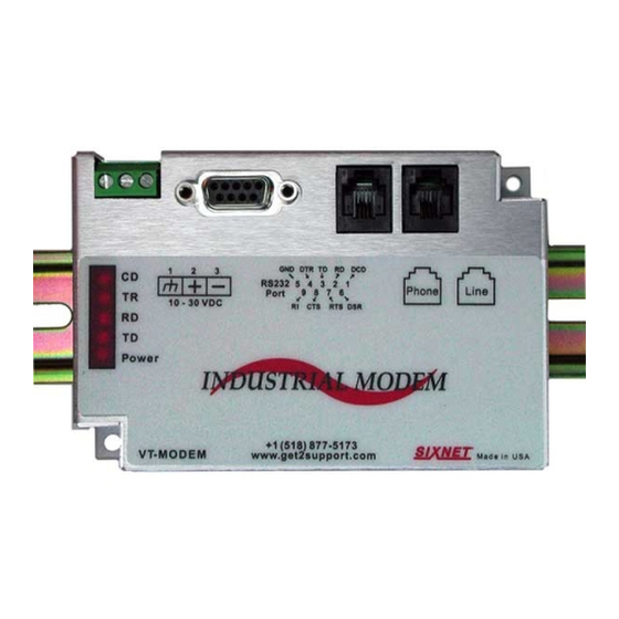
Revised 2018-12-10 Hardware Installation Drawing No. LP1087-A Mounting the VT-MODEM-4 Chapter 2 Hardware Installation 2.1 Mounting the VT-MODEM-4 The VT-MODEM-4 snaps onto standard DIN rail (DIN EN 50022) or is mounted to a flat panel using #6 or #8 screws. See the image below. The modem can be installed in any orientation, directly adjacent to other DIN rail components or in any convenient location within the enclosure. -
Page 16: Electrical Connections
DB9 male adapter that comes with the station. Cable requirements for PLCs and other devices may be different. Refer to the PLC or other device’s documentation for cable pin-outs. Some PLC cables are documented in the Technical notes provided by Red Lion technical support. -
Page 17: Ipm And St-Gt-1210 Rs232 Connections
Revised 2018-12-10 Hardware Installation Drawing No. LP1087-A Electrical Connections 2.2.2 IPm and ST‐GT‐1210 RS232 Connections An un-wired DB9M to RJ45F adapter is provided for the RS232 port on the controller. The pin-outs follow the EIA/ TIA-561 standard (see the figure below). Use this adapter along with a RJ45 male to RJ45 male straight-thru wired patch cable (not included) to make a connection between the VT-MODEM-4’s COM port (DB9 Female) and the controllers RJ45 Female RS232 port. -
Page 18: 3Rd Party Plc/Device Connections
Hardware Installation Revised 2018-12-10 Electrical Connections Drawing No. LP1087-A 2.2.3 3rd Party PLC/Device Connections Determine if the device you are connecting to is a DTE or a DCE device. Use a straight-through cable to connect the VT-MODEM to a DTE 3 party device. A cross-wired cable must be used to connect the VT-MODEM to a DCE party device. -
Page 19: Vt-Modem-4 Power, Phone Line Connections
Revised 2018-12-10 Hardware Installation Drawing No. LP1087-A Electrical Connections 2.2.4 VT‐MODEM‐4 Power, Phone Line Connections 2.2.4.1 DC POWER Connect 10 - 30 VDC to the VT-MODEM-4 as shown in the image in the section below. The modem can usually be powered from the same DC source as other devices in the enclosure. All the screw terminals should be tightened to a maximum of 3.48 in-lbs. -
Page 20: Modem Configuration
Hardware Installation Revised 2018-12-10 Modem Configuration Drawing No. LP1087-A 2.3 Modem Configuration 2.3.1 Configuring a VT‐MODEM‐4 All VT-MODEM models are factory configured to use the default communication settings for Sixnet Stations. If a VT-MODEM-4 is connected to a PLC, PC or other non-Sixnet device, then it may be necessary to reconfigure the modem. -
Page 21: To Remove A Modem
Revised 2018-12-10 Hardware Installation Drawing No. LP1087-A Modem Configuration 4. To verify that the modem has been installed, go to the “Phone and Modems” in Control Panel, then go to the “modems” tab. The modem should be listed as either a “Standard Modem” or a “Standard 28,800 bps Modem”... - Page 22 Hardware Installation Revised 2018-12-10 Modem Configuration Drawing No. LP1087-A 3. Data bits that holds the data to be transferred 4. Parity bit used for error checking and 5. 1 or 2 Stop bits that indicates the end of the data message. An example of 10-bit communication format is 9600 Baud, 8 Data bits, None Parity and 1 Stop bit.
- Page 23 Revised 2018-12-10 Hardware Installation Drawing No. LP1087-A Modem Configuration FOR THESE COM PARAMETERS SEND THESE COMMANDS Data bits Parity Stop bits AT$EB0#P0 Data bits Parity Stop bits AT$EB0#P0 Data bits Parity Stop bits AT$EB1#P2 Data bits Parity Stop bits AT$EB1#P2 Data bits Parity Stop bits...
-
Page 24: Leased Line Connections
Hardware Installation Revised 2018-12-10 Leased Line Connections Drawing No. LP1087-A 2.4 Leased Line Connections 2.4.1 Types of Leased Line connections There are two types of leased line connections that can be used with the VT-MODEM-4WW and they are described below. 1. Leased line through the telephone company Using a leased line through your telephone service provider is the best and most reliable way to communicate between two Sixnet VT-MODEM-4s because the line quality is guaranteed and maintained by the telephone company. -
Page 25: Maintenance Information
Revised 2018-12-10 Hardware Installation Drawing No. LP1087-A Maintenance Information 2.5 Maintenance Information 2.5.1 Troubleshooting Tips 2.5.1.1 VT‐MODEM Default LED Indications DEFAULT INDICATION Carrier Detect This LED will come ON once a phone line connection has been established, and will remain on for as long as the connection is maintained. Data Terminal Ready This LED will come ON when the DTR signal is present regardless the state of the &D command. -
Page 26: Service And Support Information
3.1 Service Information We sincerely hope that you never experience a problem with any Red Lion product. If you do need service, call Red Lion at 1-877-432-9908 for Technical Support. A trained specialist will help you quickly determine the source of the problem. -
Page 27: Statement Of Limited Warranty
Drawing No. LP1087-A Statement of Limited Warranty (a) Red Lion Controls Inc.(the “Company”) warrants that all Products shall be free from defects in material and workmanship under normal use for the period of time provided in “Statement of Warranty Periods” (available at www.redlion.net) current at the time of shipment of the Products (the “Warranty Period”). EXCEPT FOR THE ABOVE-STATED WARRANTY, COMPANY MAKES NO WARRANTY WHATSOEVER WITH RESPECT TO THE PRODUCTS, INCLUDING ANY (A) WARRANTY OF MERCHANTABILITY;...
Need help?
Do you have a question about the Sixnet VT-MODEM-4 and is the answer not in the manual?
Questions and answers