
Related Manuals for GORMAN-RUPP PUMPS PA6C60-4045T FT4


Summary of Contents for GORMAN-RUPP PUMPS PA6C60-4045T FT4
- Page 1 OM-07290-01 September 18, 2019 INSTALLATION, OPERATION, AND MAINTENANCE MANUAL WITH PARTS LIST PA SERIES PUMP MODEL PA6C60-4045T FT4 GORMAN‐RUPP PUMPS www.grpumps.com 2019 Gorman‐Rupp Pumps Printed in U.S.A.
- Page 2 Register your new Gorman‐Rupp pump online at www.grpumps.com Valid serial number and e‐mail address required. The engine exhaust from this product contains chemicals known to the State of California to cause cancer, birth defects or other reproductive harm. RECORD YOUR PUMP MODEL AND SERIAL NUMBER Please record your pump model and serial number in the spaces provided below.
-
Page 3: Table Of Contents
TABLE OF CONTENTS INTRODUCTION ..........PAGE I - 1 SAFETY ‐... - Page 4 TABLE OF CONTENTS (continued) PARTS LIST: Pump Model ............PAGE E - 3 Power Unit Kit .
-
Page 5: Introduction
PA SERIES OM-07290 INTRODUCTION Thank You for purchasing a Gorman‐Rupp pump. The following are used to alert personnel to proce Read this manual carefully to learn how to safely dures which require special attention, to those install and operate your pump. Failure to do so which could damage equipment, and to those could result in personal injury or damage to the which could be dangerous to personnel:... -
Page 6: Safety - Section A
PA SERIES OM-07290 SAFETY ‐ SECTION A This information applies to Prime Aire damage the pump or endanger person Series pumps. Refer to the manual ac nel as a result of pump failure. companying the engine or power source before attempting to begin oper ation. - Page 7 OM-07290 PA SERIES against a closed discharge valve, pump components will deteriorate, and the liquid could come to a boil, build pres sure, and cause the pump casing to rup Make sure the pump is level. Lower jack ture or explode. Momentary closure of a stands and chock the wheels, if so discharge valve is acceptable only equipped.
-
Page 8: Installation - Section B
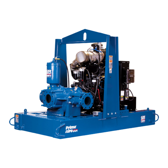
[ 1490,0 ] 58.75 POWERED BY: JOHN DEERE 4045T FT4 DIESEL ENGINE. [ 1492,2 ] Figure 1. Pump Model PA6C60-4045T FT4 PREINSTALLATION INSPECTION a. Inspect the pump for cracks, dents, damaged threads, and other obvious damage. The pump assembly was inspected and tested be... -
Page 9: Battery Installation
OM-07290 PA SERIES c. Carefully read all tags, decals, and markings POSITIONING PUMP on the pump assembly, and perform all duties indicated. Note that the pump shaft rotates in the required direction. Death or serious personal injury and damage to the pump or components can occur if proper lifting procedures Only operate this pump in the direction in... -
Page 10: Suction And Discharge Piping
PA SERIES OM-07290 to secure them when filled with liquid and under pressure. Gauges If the pump has been mounted on a mov able base, do not attempt to operate the The pump is drilled and tapped for installing dis pump unless the unit is level. -
Page 11: Sealing
OM-07290 PA SERIES Sealing air to escape from the liquid before it is drawn into the suction inlet. Since even a slight leak will affect priming, head, If two suction lines are installed in a single sump, and capacity, especially when operating with a the flow paths may interact, reducing the efficiency high suction lift, all connections in the suction line of one or both pumps. -
Page 12: Discharge Lines
PA SERIES OM-07290 Figure 2. Recommended Minimum Suction Line Submergence vs. Velocity DISCHARGE LINES Siphoning If the application involves a high discharge head, gradually close the discharge Do not terminate the discharge line at a level lower than that of the liquid being pumped unless a si throttling valve before stopping the pump. -
Page 13: Float Switch Installation
OM-07290 PA SERIES Float Switch Installation pipe is available, attach the float switch cable to the standpipe in the sump at the approxi mate desired liquid level. The Float Switch autostart system employs either a single or double float switch, where a bulb raises or lowers (floats) with the liquid level, thus activating b. - Page 14 PA SERIES OM-07290 that the liquid in the priming chamber never fully Next, install a drain line between the pump drain freezes. and the wet well or sump. This line must remain submerged in the liquid below the pump down lev The second method involves configuring the el of the liquid level control device;...
-
Page 15: Operation - Section C
OM-07290 PA SERIES OPERATION - SECTION C Review all SAFETY information in Section A. cated (see LUBRICATION in MAINTENANCE AND REPAIR). Follow the instructions on all tags, labels and The pump will begin to prime upon startup. The air decals attached to the pump. in the suction line will be discharged from the educ... -
Page 16: Operation
OM-07290 PA SERIES AL'. After the engine starts and the unit is fully Liquid Temperature And Overheating primed, adjust the engine RPM until the desired The maximum liquid temperature for this pump is flow rate is achieved. 160_ F (71_C). Do not apply it at a higher operating temperature. -
Page 17: Stopping
OM-07290 PA SERIES vacuum suction gauge readings regularly to detect against the housing. Record this temperature for strainer blockage. future reference. Never introduce air or steam pressure into the A sudden increase in bearing temperatures is a pump casing or piping to remove a blockage. This warning that the bearings are at the point of failing could result in personal injury or damage to the to operate properly. -
Page 18: Troubleshooting - Section D
OM-07290 PA SERIES TROUBLESHOOTING - SECTION D Review all SAFETY information in Section A. 5. Close the suction and discharge valves. 6. Vent the pump slowly and cau tiously. 7. Drain the pump. Before attempting to open or service the pump: 1. - Page 19 OM-07290 PA SERIES TROUBLE POSSIBLE CAUSE PROBABLE REMEDY Check strainer and clean if neces Strainer clogged. PUMP STOPS OR FAILS TO DELIVER sary. RATED FLOW OR Check and clean check valve. Discharge check valve clogged. PRESSURE (cont.) Suction intake not submerged at Check installation and correct proper level or sump too small.
-
Page 20: Preventive Maintenance
OM-07290 PA SERIES TROUBLE POSSIBLE CAUSE PROBABLE REMEDY BEARINGS RUN Bearing temperature is high, but Check bearing temperature regu TOO HOT within limits. larly to monitor any increase. Low or incorrect lubricant. Check for proper type and level of lubricant. Suction and discharge lines not prop... - Page 21 OM-07290 PA SERIES Preventive Maintenance Schedule Service Interval* Item Daily Weekly Monthly Semi‐ Annually Annually General Condition (Temperature, Unusual Noises or Vibrations, Cracks, Leaks, Loose Hardware, Etc.) Pump Performance (Gauges, Speed, Flow) Bearing Lubrication Seal Lubrication (And Packing Adjustment, If So Equipped) V‐Belts (If So Equipped) Air Release Valve Plunger Rod (If So Equipped) Front Impeller Clearance (Wear Plate)
-
Page 22: Pump Maintenance And Repair - Section E
PUMP MAINTENANCE AND REPAIR - SECTION E MAINTENANCE AND REPAIR OF THE WEARING PARTS OF THE PUMP WILL MAINTAIN PEAK OPERATING PERFORMANCE. STANDARD PERFORMANCE FOR PUMP MODEL PA6C60-4045T FT4 Based on 70_F (21_C) clear water at sea level with minimum suction lift. Since pump installations are seldom identical, your performance may be dif... - Page 23 OM-07290 PA SERIES PARTS PAGE ILLUSTRATION Figure 1. Pump Model PA6C60-4045T FT4 PAGE E - 2 MAINTENANCE & REPAIR...
- Page 24 OM-07290 PA SERIES Pump Model PA6C60-4045T FT4 PARTS LIST (From S/N 1712780 Up) ITEM PART PART NAME NUMBER PUMP END ASSEMBLY 46183-230 POWER UNIT KIT 46143-228 BATTERY SEE OPTIONS PUMP MOUNTING KIT 48157-114 NOT SHOWN: PRIME AIRE DECAL 38812-078 CAUTION DECAL 2613FJ G‐R DECAL...
- Page 25 OM-07290 PA SERIES ILLUSTRATION 32 31 30 29 Figure 2. Power Unit Kit PAGE E - 4 MAINTENANCE & REPAIR...
- Page 26 OM-07290 PA SERIES PARTS LIST Power Unit Kit ITEM PART NAME PART ITEM PART NAME PART NUMBER NUMBER JD 4045T FT4 ENGINE 29224-472 HOSE ASSEMBLY 46341-426 CNTRL PNL INSTALL KIT 48122-563 1/0 POS. CABLE ASSY 72" 47311-113 CABLE TIE 27111-218 BATT BOX ENCLOSURE 42432-013 HOSE BARB FITTING...
- Page 27 OM-07290 PA SERIES ILLUSTRATION Figure 3. Pump Assembly PAGE E - 6 MAINTENANCE & REPAIR...
- Page 28 OM-07290 PA SERIES Pump Assembly PARTS LIST ITEM PART PART NAME NUMBER PUMP END ASSEMBLY 46183-511 PRIMING CHAMBER KIT 48275-005 CHECK VALVE KIT 6" 48274-015 -CHECK VALVE 26642-134 --FLAPPER 26688-001 --COVER O‐RING 25152-377 PUMP SUPPORT BRACKET 34265-051 15080 HEX HEAD CAP SCREW B1206 15991 LOCK WASHER J12 15991...
- Page 29 OM-07290 PA SERIES ILLUSTRATION Figure 4. Pump Subassembly PAGE E - 8 MAINTENANCE & REPAIR...
- Page 30 OM-07290 PA SERIES PARTS LIST Pump Subassembly ITEM PART PART NAME NUMBER PUMP CASING SEE NOTE BELOW PIPE PLUG P08 15079 STREET ELBOW 1/2" 25412-004 STUD C1213 15991 WEAR PLATE 38691-864 11010 O‐RING 25152-453 LOCK WASHER J06 17090 HEX HEAD CAP SCREW B0604-1/2 17000 LOCK COLLAR 38115-551 15001...
- Page 31 OM-07290 PA SERIES ILLUSTRATION Ï Ï Ï Ï Ï Ï Ï Ï Ï Ï Ï Ï Ì Ì Ì Ì Ì Ï Ï Ï Ï Ì Ì Ì Ì Ì Ì Ì Ì Ì Ì Î Î Î Î Ï Î...
- Page 32 OM-07290 PA SERIES PARTS LIST Repair Rotating Assembly ITEM PART PART NAME NUMBER IMPELLER - HIGH HEAD 38615-092 11010 SEAL ASSEMBLY 46512-149 SEAL PLATE 38272-256 10000 OIL SEAL 25227-771 SIGHT GAUGE S1471 BEARING HOUSING 38251-513 10000 PIPE PLUG P08 15079 VENTED PIPE PLUG 4823A 15079 REDUCER PIPE BUSHING...
- Page 33 OM-07290 PA SERIES ILLUSTRATION Figure 6. Priming Chamber Kit PARTS LIST ITEM PART PART NAME NUMBER PRIMING CHAMBER ASSY 46112-709 PIPE BUSHING AP1608 15070 STREET ELBOW RS08 11999 BALL VALVE 26631-052 STUD C0809 15991 HEX NUT D08 15991 LOCK WASHER J08 15991 GASKET 38687-053 19060...
- Page 34 OM-07290 PA SERIES ILLUSTRATION Figure 7. Priming Chamber Assembly PARTS LIST ITEM PART PART NAME NUMBER PRIMING VALVE 26664-007 -ORIFICE BUTTON 26688-021 HEX HEAD CAP SCREW B0806 15991 LOCK WASHER J08 15991 PRIMING VALVE GASKET 38683-657 19060 PRIMING CHAMBER 38343-020 10000 STRAINER ASSEMBLY 46641-222 17000 INDICATES PARTS RECOMMENDED FOR STOCK...
- Page 35 OM-07290 PA SERIES ILLUSTRATION Ç Ç Ç Ç Î Î Î Î Ç Ç Ç Ç Î Î Î Î Î Î Î Î Î Î Î Î Ç Ç Ç Ç Î Î Î Î Î Î Î Î Ç...
- Page 36 OM-07290 PA SERIES PUMP AND SEAL DISASSEMBLY tenance procedures are used, and that any procedures not addressed in this AND REASSEMBLY manual are performed only after estab lishing that neither personal safety nor Review all SAFETY information in Section A. pump integrity are compromised by such practices.
- Page 37 OM-07290 PA SERIES Discharge Check Valve Removal and NOTE Disassembly When appropriate recycling facilities are available, the user should recycle components and fluids (Figure 3) when doing any routine maintenance / repairs and also at the end of the pump’s useful life. All other Remove the hardware (not shown) securing the components and fluids shall be disposed of ac...
- Page 38 OM-07290 PA SERIES gine. Disconnect the discharge piping from the Remove the impeller capscrew and washer (25 pump casing. and 26). Remove the hardware (7 and 8) securing the drive Install the shaft key (33) in the shaft keyway. Install flange (4) to the engine bellhousing.
- Page 39 OM-07290 PA SERIES Impeller Removal Shaft and Bearing Removal and Disassembly (Figure 5) (Figure 5) When the pump is properly operated and main tained, the bearing housing should not require dis With the rotating assembly removed from the assembly. Disassemble the shaft and bearings pump casing, unscrew the impeller (1) in a coun...
- Page 40 OM-07290 PA SERIES flammable. Use them only in a well ven be cleaned and inspected in place. It is tilated area free from excessive heat, strongly recommended that the bearings sparks, and flame. Read and follow all be replaced any time the shaft and bear precautions printed on solvent contain...
- Page 41 OM-07290 PA SERIES Install the thrust washer (20) and secure the out crews in the center of the coupling must be posi board bearing (21) to the shaft with the snap ring tioned toward the drive end of the shaft. (19).
- Page 42 OM-07290 PA SERIES Do not use petroleum‐based lubricants, or any oth The seal is not normally reused because wear pat er substance which may soften or otherwise dam terns on the finished faces cannot be realigned age the rubber. during reassembly. This could result in premature failure.
- Page 43 OM-07290 PA SERIES RETAINER SEAL PLATE SPRING O‐RINGS IMPELLER SLEEVE O‐RING IMPELLER SHIMS IMPELLER SHAFT INTEGRAL SHAFT ROTATING SLEEVE ELEMENT BELLOWS SPRING CENTERING WASHER STATIONARY SEAT DRIVE BAND Figure 10. Seal Assembly the O‐ring down the shaft until it seats against the shaft shoulder.
- Page 44 OM-07290 PA SERIES Lubricate the O‐rings (6 and 15) with light grease and install them in the grooves in the wear plate and back cover. The shaft and impeller threads must be Clearance between the impeller and wear plate is adjusted using the four back cover nuts (13) and completely clean before reinstalling the im...
- Page 45 OM-07290 PA SERIES adjusting screws so the holes in the collars for the Install the cover O‐ring and secure the cover with locking screws align approximately with the holes the previously removed hardware. in the cover plate. Apply a small amount of light grease to the gasket Loosen the back cover nuts used to press the back to hold it in place and position it against the pump cover into the pump casing one full turn.
- Page 46 OM-07290 PA SERIES LUBRICATION NOTE The white reflector in the sight gauge must be posi (Figure 4) tioned horizontally to provide proper drainage. Seal Assembly Under normal conditions, drain the bearing hous Fill the seal cavity through the hole for the vented ing once each year and refill with clean oil.
- Page 47 For Warranty Information, Please Visit www.grpumps.com/warranty or call: U.S.: 419-755-1280 Canada: 519-631-2870 International: +1-419-755-1352 GORMAN‐RUPP PUMPS...
Need help?
Do you have a question about the PA6C60-4045T FT4 and is the answer not in the manual?
Questions and answers