
Subscribe to Our Youtube Channel
Related Manuals for GORMAN-RUPP PUMPS PA4A60-4024T


Summary of Contents for GORMAN-RUPP PUMPS PA4A60-4024T
- Page 1 OM-06415-02 July 6, 2016 INSTALLATION, OPERATION, AND MAINTENANCE MANUAL WITH PARTS LIST PA SERIES PUMP MODEL PA4A60-4024T GORMAN‐RUPP PUMPS www.grpumps.com 2016 Gorman‐Rupp Pumps Printed in U.S.A.
- Page 2 Register your new Gorman‐Rupp pump online at www.grpumps.com Valid serial number and e‐mail address required. The engine exhaust from this product contains chemicals known to the State of California to cause cancer, birth defects or other reproductive harm. RECORD YOUR PUMP MODEL AND SERIAL NUMBER Please record your pump model and serial number in the spaces provided below.
-
Page 3: Table Of Contents
TABLE OF CONTENTS INTRODUCTION ..........PAGE I - 1 SAFETY ‐... - Page 4 TABLE OF CONTENTS (continued) STOPPING ..............PAGE C - 4 Manual Stopping .
-
Page 5: Introduction
PA SERIES OM-06415 INTRODUCTION Thank You for purchasing a Gorman‐Rupp pump. HAZARD AND INSTRUCTION Read this manual carefully to learn how to safely DEFINITIONS install and operate your pump. Failure to do so could result in personal injury or damage to the The following are used to alert maintenance per... -
Page 6: Safety - Section A
PA SERIES OM-06415 SAFETY ‐ SECTION A This information applies to Prime Aire the positive battery cable before per Series pumps. Refer to the manual ac forming any maintenance. Failure to do companying the engine or power so may result in serious personal injury. source before attempting to begin oper... - Page 7 OM-06415 PA SERIES certain that the pump and all piping or fingers or tools, causing severe injury to hose connections are tight, properly personnel. supported and secure before operation. Make sure the pump is level. Lower jack Do not operate the pump against a stands and chock the wheels, if so closed discharge valve.
-
Page 8: Installation - Section B
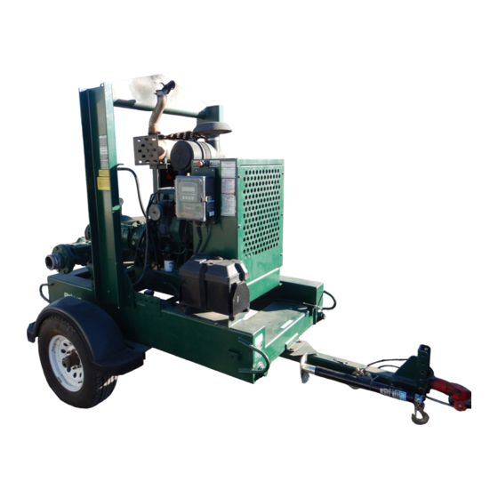
See Figure 1 for the approximate physical dimen some of the information such as mounting, line sions of this pump. OUTLINE DRAWING Figure 1. Pump Model PA4A60-4024T PREINSTALLATION INSPECTION a. Inspect the pump for cracks, dents, damaged threads, and other obvious damage. -
Page 9: Battery Installation
OM-06415 PA SERIES c. Carefully read all tags, decals, and markings POSITIONING PUMP on the pump assembly, and perform all duties indicated. Note that the pump shaft rotates in the required direction. Death or serious personal injury and damage to the pump or components can occur if proper lifting procedures Only operate this pump in the direction in... -
Page 10: Suction And Discharge Piping
PA SERIES OM-06415 to secure them when filled with liquid and under pressure. Gauges If the pump has been mounted on a mov able base, do not attempt to operate the The pump is drilled and tapped for installing dis pump unless the unit is level. -
Page 11: Sealing
OM-06415 PA SERIES Sealing air to escape from the liquid before it is drawn into the suction inlet. Since even a slight leak will affect priming, head, If two suction lines are installed in a single sump, and capacity, especially when operating with a the flow paths may interact, reducing the efficiency high suction lift, all connections in the suction line of one or both pumps. -
Page 12: Discharge Lines
PA SERIES OM-06415 Figure 2. Recommended Minimum Suction Line Submergence vs. Velocity DISCHARGE LINES Siphoning If the application involves a high discharge head, gradually close the discharge Do not terminate the discharge line at a level lower than that of the liquid being pumped unless a si throttling valve before stopping the pump. -
Page 13: Float Switch Installation
OM-06415 PA SERIES Float Switch Installation pipe is available, attach the float switch cable to the standpipe in the sump at the approxi mate desired liquid level. The Float Switch autostart system employs either a single or double float switch, where a bulb raises or lowers (floats) with the liquid level, thus activating b. - Page 14 PA SERIES OM-06415 that the liquid in the priming chamber never fully Next, install a drain line between the pump drain freezes. and the wet well or sump. This line must remain submerged in the liquid below the pump down lev The second method involves configuring the el of the liquid level control device;...
-
Page 15: Operation - Section C
OM-06415 PA SERIES OPERATION - SECTION C OPERATION Make sure the pump is level. Lower the jack stands and chock the wheels, if so equipped. Review all SAFETY information in Section A. Follow the instructions on all tags, labels and decals attached to the pump. -
Page 16: Operation In Extreme Heat
OM-06415 PA SERIES and system operating pressure. Do not operate Leakage below the recommended operating speed (if appli cable). Once the pump is fully primed, no leakage should be visible at pump mating surfaces, or at pump connections or fittings. Keep all line connections and fittings tight to maintain maximum pump effi... -
Page 17: Strainer Check
OM-06415 PA SERIES Strainer Check Should any of the safety features cause the engine to shut down, the cause must be determined and corrected before putting the unit back into service. Check the strainer regularly, and clean it as neces sary. - Page 18 OM-06415 PA SERIES tenance and Repair). Bearing overheating can COLD WEATHER PRESERVATION also be caused by shaft misalignment and/or ex cessive vibration. If the pump will be idle for an extended period of When pumps are first started, the bearings may time in below freezing conditions, drain the pump seem to run at temperatures above normal.
- Page 19 OM-06415 PA SERIES TROUBLESHOOTING - SECTION D Review all SAFETY information in Section A. 5. Close the suction and discharge valves. 6. Vent the pump slowly and cau tiously. 7. Drain the pump. Before attempting to open or service the pump: 1.
- Page 20 OM-06415 PA SERIES TROUBLE POSSIBLE CAUSE PROBABLE REMEDY Check strainer and clean if neces Strainer clogged. PUMP STOPS OR FAILS TO DELIVER sary. RATED FLOW OR Check and clean check valve. Discharge check valve clogged. PRESSURE (cont.) Suction intake not submerged at Check installation and correct proper level or sump too small.
- Page 21 OM-06415 PA SERIES TROUBLE POSSIBLE CAUSE PROBABLE REMEDY BEARINGS RUN Bearing temperature is high, but Check bearing temperature regu TOO HOT within limits. larly to monitor any increase. Low or incorrect lubricant. Check for proper type and level of lubricant. Suction and discharge lines not prop...
- Page 22 OM-06415 PA SERIES Preventive Maintenance Schedule Service Interval* Item Daily Weekly Monthly Semi‐ Annually Annually General Condition (Temperature, Unusual Noises or Vibrations, Cracks, Leaks, Loose Hardware, Etc.) Pump Performance (Gauges, Speed, Flow) Bearing Lubrication Seal Lubrication (And Packing Adjustment, If So Equipped) V‐Belts (If So Equipped) Air Release Valve Plunger Rod (If So Equipped) Front Impeller Clearance (Wear Plate)
- Page 23 PUMP MAINTENANCE AND REPAIR - SECTION E MAINTENANCE AND REPAIR OF THE WEARING PARTS OF THE PUMP WILL MAINTAIN PEAK OPERATING PERFORMANCE. STANDARD PERFORMANCE FOR PUMP MODEL PA4A60-4024T Based on 70_F (21_C) clear water at sea level Contact the Gorman‐Rupp Company to verify per...
- Page 24 OM-06415 PA SERIES PARTS PAGE ILLUSTRATION Figure 1. Pump Model PA4A60-4024T PAGE E - 2 MAINTENANCE & REPAIR...
- Page 25 OM-06415 PA SERIES Pump Model PA4A60-4024T PARTS LIST (From S/N 1584665 Up) ITEM PART PART NAME NUMBER PUMP END ASSEMBLY 46133-518 POWER UNIT KIT 46143-127 BATTERY SEE OPTIONS G‐R DECAL GR-06 PRIME AIRE DECAL 38812-078 PUMP MOUNTING KIT 48157-026 NOT SHOWN: G‐R DECAL...
- Page 26 OM-06415 PA SERIES ILLUSTRATION Figure 2. 46143-127 Power Unit Kit PAGE E - 4 MAINTENANCE & REPAIR...
- Page 27 OM-06415 PA SERIES PARTS LIST 46143-127 Power Unit Kit ITEM PART PART NAME NUMBER JOHN DEERE ENGINE 29224-403 BASE/FUEL TANK ASSY 41553-005 24150 LIFTING BAIL KIT 48274-803 BATTERY BOX ASSY 42432-005 FUEL PICKUP 29332-145 FUEL GAUGE 29332-131 HEX HD CAPSCREW B1007 15991 LOCK WASHER J10 15991...
- Page 28 OM-06415 PA SERIES ILLUSTRATION Figure 3. 46133-518 Pump End Assembly PAGE E - 6 MAINTENANCE & REPAIR...
- Page 29 OM-06415 PA SERIES 46133-518 Pump End Assembly PARTS LIST ITEM PART PART NAME NUMBER PUMP ASSEMBLY 64C60-(SAE 4/10) FLANGE GASKET 1676G 18000 STUD C1011 15991 HEX NUT D10 15991 LOCK WASHER J10 15991 SPOOL 38644-802 10000 CHECK VALVE KIT 48274-003 -FLANGE GASKET 25113-034 -CHECK VALVE...
- Page 30 OM-06415 PA SERIES ILLUSTRATION Figure 4. 64C60-(SAE 4/10) Pump Assembly PAGE E - 8 MAINTENANCE & REPAIR...
- Page 31 OM-06415 PA SERIES PARTS LIST 64C60-(SAE 4/10) Pump Assembly ITEM PART PART NAME NUMBER PUMP CASING SEE NOTE BELOW WEAR PLATE ASSY 10532B 15990 REPAIR ROTATING ASSY 44163-594 LOCK WASHER J06 15991 HEX NUT D06 15991 O‐RING 25154-273 O‐RING S1674 SHIM SET 13130 17040 LOCK WASHER...
- Page 32 OM-06415 PA SERIES ILLUSTRATION Figure 5. 44163-229 Repair Rotating Assembly PAGE E - 10 MAINTENANCE & REPAIR...
- Page 33 OM-06415 PA SERIES PARTS LIST 44163-594 Repair Rotating Assembly ITEM PART PART NAME NUMBER IMPELLER 10528 11010 IMP ADJ SHIM SET 37J 17090 CART SEAL ASSY 46513-151 SEAL PLATE 38272-234 10010 GASKET 10959G 20000 OIL SEAL S1352 OIL SEAL S1352 OIL SEAL S1352 LOCK WASHER...
- Page 34 OM-06415 PA SERIES ILLUSTRATION Figure 6. 48275-005 Priming Chamber Kit PARTS LIST ITEM PART PART NAME NUMBER PRIMING CHAMBER ASSY 46112-709 PIPE BUSHING AP1608 11999 STREET ELBOW RS08 11999 BALL VALVE 26631-052 STUD C0809 15991 HEX NUT D08 15991 LOCK WASHER J08 15991 GASKET 38687-053 19060...
- Page 35 OM-06415 PA SERIES ILLUSTRATION Figure 7. 46112-709 Priming Chamber Assembly PARTS LIST ITEM PART PART NAME NUMBER PRIMING VALVE 26664-007 -ORIFICE BUTTON 26688-021 HEX HD CAPSCREW B0806 15991 LOCKWASHER J08 15991 PRIMING VALVE GASKET 38683-657 19060 PRIMING CHAMBER 38343-020 10000 STRAINER ASSY 46641-222 17000 INDICATES PARTS RECOMMENDED FOR STOCK...
- Page 36 OM-06415 PA SERIES ILLUSTRATION 0.25 IN. Figure 8. 44162-160 Drive Assembly PARTS LIST ITEM PART PART NAME NUMBER COUPLING KIT 48112-005 -BUSHING 24131-496 -COUPLING ASSEMBLY 24391-105 LOCK WASHER 21171-536 SOCKET HEAD CAPSCREW BD0606-1/2 15991 SOCKET HEAD CAPSCREW 22644-220 HEX HD CAPSCREW B0605 15991 HEX HD CAPSCREW 22645-164...
- Page 37 OM-06415 PA SERIES PUMP AND SEAL DISASSEMBLY pump integrity are compromised by such practices. AND REASSEMBLY Review all SAFETY information in Section A. Follow the instructions on all tags, label and de cals attached to the pump. Before attempting to open or service the pump: This pump requires little service due to its rugged, 1.
- Page 38 OM-06415 PA SERIES charge check valve assembly and gasket (not authorized parts may result in damage to shown) from the pump assembly (1). the equipment and/or injury to personnel and will invalidate the warranty. The flapper and cover O‐ring are the only service able parts of the check valve.
- Page 39 OM-06415 PA SERIES Position a clean container under the seal cavity Pump Casing and Wear Plate Removal drain plugs (11, Figure 4 and 15A, Figure 5). Re (Figure 4) move the plugs and drain the oil from the seal cav ity into the container.
- Page 40 OM-06415 PA SERIES the bearing housing (9). Position the seal plate on a be replaced any time the shaft and bear flat surface with the impeller side down. Use a ings are removed. wooden dowel or other suitable tool to press on the Clean the bearing housing, shaft and all compo...
- Page 41 OM-06415 PA SERIES drive end of the shaft. Heat the bearings to a uniform temperature no Most cleaning solvents are toxic and higher than 250 F (120 C) and slide the bearings onto the shaft, one at a time, until they are fully flammable.
- Page 42 OM-06415 PA SERIES Apply a light coating of oil to the lip of the outboard condition can cause premature bearing oil seal (6) and press it into the bearing housing failure. bore with the lip positioned as shown in Figure 5. The end of the shaft must be recessed Press the oil seal into the housing until the face is 0.25 inch (6,3 mm) from the face of the...
- Page 43 OM-06415 PA SERIES sparks, and flame. Read and follow all A new seal assembly should be installed precautions printed on solvent contain any time the old seal is removed from the ers. pump. Wear patterns on the finished faces cannot be realigned during reassembly. Clean the seal cavity and shaft with a cloth soaked Reusing an old seal could result in prema...
- Page 44 OM-06415 PA SERIES the external stationary seat O‐ring engages the STATIONARY SEAT FULLY SEATED IN bore in the seal plate. SEAL PLATE BORE Clean and inspect the impeller as described in Im peller Installation and Adjustment. Install half of the set of impeller shims (2) provided with the seal, and screw the impeller onto the shaft until it is seated against the seal (see Figure 11).
- Page 45 OM-06415 PA SERIES A clearance of .025 to .040 inch (0,64 to 1,02 mm) lows will adhere to the sleeve during use, between the impeller and the seal plate is neces and attempting to separate them could sary for maximum pump efficiency. Measure this damage the bellows.
- Page 46 OM-06415 PA SERIES Apply a small amount of light grease to the dis LUBRICATION charge flange gasket to hold it in place and posi Seal Assembly tion it against the pump casing flange. Support the (Figure 5) discharge check valve assembly using a sling and a suitable lifting device.
- Page 47 For Warranty Information, Please Visit www.grpumps.com/warranty or call: U.S.: 419-755-1280 Canada: 519-631-2870 International: +1-419-755-1352 GORMAN‐RUPP PUMPS...
Need help?
Do you have a question about the PA4A60-4024T and is the answer not in the manual?
Questions and answers