Advertisement
Quick Links
The SI3500 is a member of the SI3000 Readout Family.
All members of the family are marked SI3000 on the front panel.
This manual is specifically for the SI3500 Model with Digital Orbit Interface
user and installation manual
SI3500
SI3500
ORBIT® Digital Display
Advertisement

Related Manuals for Ametek Solarton Metrology Oribt SI3500


Summary of Contents for Ametek Solarton Metrology Oribt SI3500
- Page 1 SI3500 SI3500 ORBIT® Digital Display The SI3500 is a member of the SI3000 Readout Family. All members of the family are marked SI3000 on the front panel. This manual is specifically for the SI3500 Model with Digital Orbit Interface user and installation manual...
- Page 2 Index Section Title Page Section Title Page Index ..... 1 Input/Output Menu ....25 Serial Port Menu .
- Page 3 2.0 Safety Information Terms in this Manual WARNING statements identify conditions or practices that could result in personal injury or loss of life. CAUTION statements identify conditions or practices that could result in damage to the equipment or other property. Symbols in this Manual This symbol indicates where applicable cautionary or other information is to be found.
- Page 4 2.0 Safety Information (cont.) WARNINGS: Do not operate in an explosive atmosphere Do not remove covers or panels To avoid personal injury, do not remove covers and panels. Do not operate the equipment without the covers and panels fitted. There are no internal adjustments required during commissioning of the equipment.
- Page 5 3.0 Service and Repair This equipment contains no user serviceable parts. This equipment must be returned to your Solartron dealer for any service and repair. The SI3500 is designed to be maintenance free. Contact with solvents should be avoided. Any attempt to dismantle the SI3500 will invalidate the warranty.
- Page 6 4.0 Bench Mounted or Installed into a Panel 4.1 Bench Mounted with associated Solartron Orbit® Digital Probes and power supply 4.0 Bench Mounted or Installed into a Panel 502783 issue 5...
- Page 7 4.0 Bench Mounted or Installed into a Panel (cont.) 4.2 Panel Mounting - Ensure that there is sufficient space behind the relevant instrument panel for the SI3500 and its cabling (refer to section 4.3 for dimensions). - Cut out the panel aperture to the dimensions shown. - Working from behind the panel, with the box fully located, fit the side brackets to the studs and slide them forward toward the panel until they lock into place.
- Page 8 4.0 Bench Mounted or Installed into a Panel (cont.) 4.3 Panel Dimensions 4.0 Bench Mounted or Installed into a Panel (cont.) 502783 issue 5...
- Page 9 4.0 Bench Mounted or Installed into a Panel (cont.) 4.4 Assembly Dimensions 4.0 Bench Mounted or Installed into a Panel (cont.) 502783 issue 5...
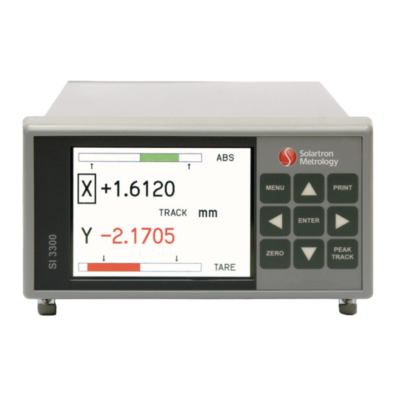
- Page 10 5.0 Display Panel 5.1 Layout of Front Panel Liquid Crystal Operator Colour Display Return to Setup Menu Scroll Up (Moves cursor around screen), Apply Preset (ABS/PRE) Print Option Enter Scroll Right (select option) Track, Peak+, Peak-, Diff Scroll Down (Moves cursor around screen) Zero (ABS/TARE) 10 Scroll Left (select option) 5.0 Display Panel...
- Page 11 5.0 Display Panel (cont.) 5.2 Layout of Rear Panel 11 Screen Earth 12 Input/Output Connection 13 RS232 Communications 14 24V DC ON/OFF Switch 15 24V DC Supply 16 Orbit Connection 17 Orbit Connection 5.0 Display Panel (cont.) 502783 issue 5...
- Page 12 5.0 Display Panel (cont.) 5.3 Overview of Features Transducers 1 or 2 transducers may be connected SI3100 Series LVDT (Note: when setting up LVDT enter sensitivity in mV/V/mm regardless of final choice of measurement units) SI3300 Series 4-20 mA or DC inputs (0-5 V, 0-10 V, ±5 V, ±10 V) SI3500 Series –...
- Page 13 5.0 Display Panel (cont.) 5.3 Overview of Features (cont.) Functions The SI3000 series has the following functions available from the font panel keypad or controllable from the RS232 and some discrete inputs. Zero: Allows a reading to be set to zero (display shows TARE) all measurements are then referenced to the zero position. Print: Allows measured data to be printed via the RS232 port.
- Page 14 6.0 Operating Screen Display seen directly after powering up Note: This screen will vary depending on the Operator Screen displayed prior to powering down Press MENU go to 6.1 6.0 Operating Screen 502783 issue 5...
- Page 15 6.0 Operating Screen (cont.) 6.1 MENUS and SETUPS Scroll up or down using the keys to the required sub menu PRESS (ENTER) Probes 6.2 Measurement 6.3 Selects the type of probes to be Selects Measurement type. A,B,(A+B) etc. used with this instrument, the Measurement Mode (Track, Peak+, Peak-, Diff) parameters, channels and Identifica- Reset Mode (Manual/Auto)
- Page 16 6.0 Operating Screen (cont.) 6.2 Probes Channel A to move the cursor around the screen. to select options. e.g. Extend + or Retract+ NONE see 6.2.1 EXTEND + Preset by Probe (Orbit) To confirm Probe ID, register a new Probe or Probe ID blank. Select NOTIFY, Press Enter Follow Screen Instructions Press ENTER see 6.2.2...
- Page 17 6.0 Operating Screen (cont.) 6.2.1 Probe Type Channel A to move the cursor around the screen. to select options. Orbit® see 6.2 Press ENTER see 6.2.2 Probes menu Channel B 6.0 Operating Screen (cont.) 502783 issue 5...
- Page 18 6.0 Operating Screen (cont.) 6.2.2 Probes Channel B to move the cursor around the screen. to select options. e.g. Extend + or Retract+ Orbit see 6.2 Extend + or Retract+ Preset by Probe (Orbit) Preset by Probe (Orbit) Press ENTER see 6.2 Back to Channel A Press ENTER see 6.1 Back to Setup Menu...
- Page 19 6.0 Operating Screen (cont.) 6.2.2.1 Probe type Channel B to move the cursor around the screen. to select options. Orbit see 6.2.2 Press ENTER see 6.1 Press ENTER see 6.2 Back to Setup Menu Back to Channel A 6.0 Operating Screen (cont.) 502783 issue 5...
- Page 20 6.0 Operating Screen (cont.) 6.3 Measurement Menu Page 1 to move the cursor around the screen. to select options. Orbit see 6.2 (Distance)B,A+B,(A+B)/2,A-B,(A-B)/2 (B-A)/a (Angle = limited to 5 deg) PEAK + , PEAK -, or Diff see 6.3.1 / 6.9 Press ENTER Go to Measurement Menu Page 2 see 6.3.2 6.0 Operating Screen (cont.)
- Page 21 6.0 Operating Screen (cont.) 6.3.1 Measurement Menu Page 1 to move the cursor around the screen. to select options. Measure Type B,A+B,(A+B)/2,A-B,(A-B)/2, (B-A)/a (Shows on Operator Screen in mm, inch for distance) (Shows on Operator Screen in rad, deg for angle) Measure Mode Track, Peak+, Peak-, Diff Auto, Manual Auto Mode only...
- Page 22 6.0 Operating Screen (cont.) 6.3.2 Measurement (Distance) Menu Page 2 to move the cursor around the screen. to select options. Measure Type B,A+B,(A+B)/2,A-B,(A-B)/2, (B-A)/a (Shows on Operator Screen in mm, inch for distance) (Shows on Operator Screen in rad, deg for angle) Measure Mode Track, Peak+, Peak-, Diff Auto, Manual Diff Mode only...
- Page 23 6.0 Operating Screen (cont.) 6.3.3 Measurement (Distance) Menu Page 2 to move the cursor around the screen. to select options. Orbit see 6.2 Bipolar, Unipolar or Auto Mode Bipolar selected Measurement range displayed Top + xx mm/inch Bottom - xx mm/inch Centrally Tracks the +/- measurements within limits in green turning to red when outside the limits, flashes OVER/UNDER when outside the Measurement range.
- Page 24 6.0 Operating Screen (cont.) 6.3.4 Measurement (Angle) Menu Page 2 to move the cursor around the screen. to select options. rad, deg (used for angle measurement (B-A)/a) Bipolar, Unipolar or Auto Mode Bipolar selected Measurement range displayed Top + xx rad/deg Bottom - xx rad/deg Centrally Tracks the +/- measurements within limits in green turning to red when outside the limits, flashes...
- Page 25 6.0 Operating Screen (cont.) 6.4 Limit Menu to move the cursor around the screen. to select options. 3 types of limits can be displayed A,B and "Computed Limits" when more than one measurement type selected see 6.3 Press ENTER to Edit parameter To move cursor To increment/decrement numbers To change +/-...
- Page 26 6.0 Operating Screen (cont.) 6.5 Input/Output Menu to move the cursor around the screen. to select options. Active High Active High 0 to 10V, -5 to +5V -10 to +10V 4-20mA 0 to 10V, -5 to +5V -10 to +10V 4-20mA Continuous Press ENTER see 6.1 Back to Setup Menu...
- Page 27 6.0 Operating Screen (cont.) 6.6 Serial Port Menu to move the cursor around the screen. to select options. 2400,4800,9600,19200,38400 0.5, 1.5,2 odd, even Press ENTER see 6.1 Back to Setup Menu 6.0 Operating Screen (cont.) 502783 issue 5...
- Page 28 6.0 Operating Screen (cont.) 6.7 Display Menu - Screen 1 to move the cursor around the screen. to select options. Varies the screen 0,5,10,15,20,25,30,35,40,45,50,55 contrast for optimum 60,65,70,75,80,85,90,95,100 operator viewing screen Press ENTER to Edit parameter To move cursor Offsets bar + or - To increment/decrement numbers Switches Bar Auto Range On/Off...
- Page 29 6.0 Operating Screen (cont.) 6.7 Display Menu - Screen 2 to move the cursor around the screen. to select options. On, Off Press ENTER to Edit number To move cursor To increment/decrement number To change +/- Press ENTER to Exit Mode On, Off (see section 6.10) Select Back/Exit Menu Enter to Action...
- Page 30 6.0 Operating Screen (cont.) 6.8 Utilities Menu to move the cursor around the screen. to select options. Press ENTER To Restore Factory Default Settings see 6.8.3 Set Password Set up Data Log mode Press ENTER see 6.1 Back to Setup Menu 6.0 Operating Screen (cont.) 502783 issue 5...
- Page 31 6.0 Operating Screen (cont.) 6.8.1 Password Menu to move the cursor around the screen. to select options. Keys to turn On/Off Default set to 1234 Use ENTER and keys to change, Press ENTER to confirm Lock Menu, Lock ALL Note: If Lock ALL is applied all keypad functions are disabled except menu screen.
- Page 32 6.0 Operating Screen (cont.) 6.8.2 Password Entry Note: Only seen if password enabled to move the cursor around the screen. to select options. Press to select parameter Press ENTER see 6.1 Back to Setup Menu 6.0 Operating Screen (cont.) 502783 issue 5...
- Page 33 6.0 Operating Screen (cont.) 6.8.3 Utilities Menu (Factory Default Restore) The following is displayed for 3 seconds, the unit automatically defaults to factory setting and returns to the Operator Screen. 6.0 Operating Screen (cont.) 502783 issue 5...
- Page 34 6.0 Operating Screen (cont.) 6.9 Operator Screen Selected Measurement Menu see 6.3 Track PEAK+,PEAK-,DIFF Selected at Measurement menu see 6.3 or PEAK/TRACK membrane on keypad TRACK Measures actual distance/angle within the set limits displaying green. Turning red when outside the set limits. Returning to green when back inside the limits.
- Page 35 6.0 Operating Screen (cont.) 6.10 X Y Mode Press Zero to TARE Press to apply Preset (see 6.7) or ABS (Absolute) Transducer X measurement To select channel for Zero etc. Transducer Y measurement 6.0 Operating Screen (cont.) 502783 issue 5...
- Page 36 6.0 Operating Screen (cont.) 6.11 Logging Menu Page 1 to select Standard, Start on Discrete Input or Trigger on Discreet Input to select On, Off Press ENTER to edit number To Move Count To Increment Number Press ENTER to Exit mode 6.0 Operating Screen (cont.) 502783 issue 5...
- Page 37 6.0 Operating Screen (cont.) 6.12 Logging Menu Page 2 to move to option Press ENTER to Select option 6.0 Operating Screen (cont.) 502783 issue 5...
- Page 38 7.0 RS232 User Input Commands The unit shall respond to the following RS232 User Input Commands Command Command Number of Description Sequence Parameter Bytes Print '^''O' Print Mode = Normal : Standard print Print Mode = C55 : C55 compatible print (Print Mode option is located in the 'serial port' menu) Extended Print '^''P'...
- Page 39 7.0 RS232 User Input Commands (cont.) 7.1 RS232 User Command Details In the following table sp is used to mean an Ascii space (Dec 32 Hex 20) Shaded cells mean they are not used for the command shown Command Total No of Chars Character Number Print Extended Print...
- Page 40 7.0 RS232 User Input Commands (cont.) 7.1 RS232 User Command Details (cont.) In the following table sp is used to mean an Ascii space (Dec 32 Hex 20) Command Total No of Chars Character Number SetUnit Set Limits Set Ch A UL Set Ch A LL Set Ch B UL Set Ch B LL...
- Page 41 7.0 RS232 User Input Commands (cont.) 7.1 RS232 User Command Details (cont.) X = Value eg 3.4 pad with spaces Total No of Command Character Number Chars Zero Peak Reset Start Continuous Print Stop Continuous Print Set Print Key Single Mode Set Print Key Cont Mode Set I/O Logic State Logic Inputs Active Low...
- Page 42 7.0 RS232 User Input Commands (cont.) 7.2 RS232 Output Formats PRINT OUTPUT FORMATS C55 Compatible Format Sign Reading: right aligned, DP set by precision Units Limit \n Example +0.00017mm ● -0.0017mm ● -0.017mm ● NORMAL Format Sign Reading: right aligned, DP set by precision Units Limit +1.1308mm...
- Page 43 7.0 RS232 User Input Commands (cont.) 7.2 RS232 Output Formats 9 10 11 12 13 14 15 16 17 18 19 20 21 22 23 24 25 26 27 28 29 30 31 32 33 EXTENDED Format Sign Reading: right aligned, DP set by precision Units Reading Type Mode...
- Page 44 8.0 Interface Connections 8.1 I/O CONNECTOR (Mounted on I/O Board) 25 WAY D TYPE SOCKET, FIXED TO REAR PANEL DESCRIPTION DETAIL CH1 OVER RANGE CH1 IN RANGE CH1 UNDER RANGE CH2 OVER RANGE CH2 IN RANGE CH2 UNDER RANGE Isolated O/P Common ‘Zero key’...
- Page 45 8.0 Interface Connections (cont.) 8.2 COMMS CONNECTOR 9 WAY D TYPE PCB SOCKET, FIXED TO REAR PANEL RS232 CONFIGURATION Not Used RS232 Tx RS232 Rx Not Used RS232 GND Not Used Not Used Not Used Not Used 8.3 POWER CONNECTOR (Mounted on rear panel) 2.5 mm Chassis Mounted DC skt DESCRIPTION DETAIL...
- Page 46 8.0 Interface Connections (cont.) 8.4 ORBIT® Connectors 2 off 9 way D Type Sockets in recess under rear panel ORBIT CONNECTION (From Orbit Adapter) DESCRIPTION Not Used RS485 A RS485 B Not Used Not Used 8.0 Interface Connections (cont.) 502783 issue 5...
- Page 47 9.0 Technical Specification MAIN INSTRUMENT Display Type Colour LCD with integral backlight. Display Length (mm) ±ABCD.EFGHJ Display Length (inches) ±ABCD.EFGHJK Resolution - Display 0.05µm or 0.000005” Analogue Display Solid Vertical bar Keypad 9 key membrane keypad (Print, Zero, Peak/Track, Enter, Menu and navigation keys) Temperature Storage temperature range: -20°C to +85°C, Operating temperature range: 0°C to +50°C IP Rating...
Need help?
Do you have a question about the Solarton Metrology Oribt SI3500 and is the answer not in the manual?
Questions and answers