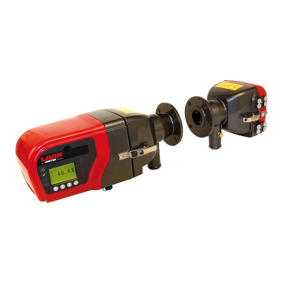
Summary of Contents for Ametek LAND 4500 MkIII
-
Page 1: Installation Guide
Model 4500 MkIII Main PCB (Part Nº 804320) Installation Guide Publication Nº 809352 Language: English Issue 2 28 July 2017 © Land Instruments International, 2010-2017... - Page 2 IMPORTANT INFORMATION - PLEASE READ Health and Safety Information Read all of the instructions in this booklet - including all the WARNINGS and CAUTIONS - before using this product. If there is any instruction which you do not understand, DO NOT USE THE PRODUCT.
- Page 3 Web: www.landinst.com For further details on all AMETEK Land offices, distributors and representatives, please visit our websites. Return of Damaged Goods IMPORTANT If any item has been damaged in transit, this should be reported to the carrier and to the supplier immediately.
- Page 4 Model 4500 MkIII Installation Guide Main PCB...
-
Page 5: Table Of Contents
Installation Guide Model 4500 MkIII Main PCB Contents Introduction Removing the transceiver cover Replace the circuit board Adjust the LED intensity Adjusting the LED with a Modbus Connection Adjusting the LED without a Modbus Connection Replace the instrument cover Reconfigure and Recalibrate the Instrument... - Page 6 Model 4500 MkIII Installation Guide Main PCB...
-
Page 7: Introduction
Installation Guide Model 4500 MkIII Main PCB Introduction This Installation Guide provides information on how to remove and replace the Main PCB (Part Nº 804320) in a Land Instruments International Model 4500 MkIII Continuous Opacity Monitoring System (COMS). CAUTION This procedure is intended for skilled instrument technicians and should be carried out in a clean workshop. -
Page 8: Replace The Circuit Board
Model 4500 MkIII Installation Guide Main PCB Replace the circuit board Make sure you can identify each of the connectors before you disconnect them. If in doubt, label each connector. Using a 3 mm Allen key, remove the 6 mounting screws and remove the old circuit board Fit the new circuit board using... -
Page 9: Adjust The Led Intensity
Installation Guide Model 4500 MkIII Main PCB Adjust the LED intensity There are two methods available for adjusting the intensity of the LED: • Adjusting the LED with a Modbus connection (preferred) • Adjusting the LED without a Modbus connection (for use if a Modbus connection is not possible) 4.1 Adjusting the LED with a Modbus Connection Connect a cable terminal to the... -
Page 10: 4.2 Adjusting The Led Without A Modbus Connection
Model 4500 MkIII Installation Guide Main PCB 4.2 Adjusting the LED without a Modbus Connection Carefully replace the cover, ensuring that it doesn’t jam on any components When the cover is close enough, refit the keyboard connector ribbon, ensuring it is not offset by one pin. DO NOT FASTEN THE COVER SCREWS AT THIS POINT. -
Page 11: Replace The Instrument Cover
Installation Guide Model 4500 MkIII Main PCB Replace the instrument cover Carefully replace the cover, ensuring that it doesn’t jam on any components. When the cover is close enough, refit the keyboard connector ribbon. Ensure the white cord seal is correctly seated before pushing the cover home. - Page 12 Gas Monitoring Products Standard Terms of Warranty Land Instruments International warrant all products of our own manufacture to be within specified limits of calibration, if any, when despatched from our works. Also that they are free from defects in material and workmanship for normal use and service when used for their intended purpose within the limits of our specification.


Need help?
Do you have a question about the LAND 4500 MkIII and is the answer not in the manual?
Questions and answers