
Related Manuals for YEONHWA M TECH XP-400D


Summary of Contents for YEONHWA M TECH XP-400D
- Page 1 User Manual UHF Transceiver XP-400D YeonHwa M Tech Co.,Ltd Version #1 (2016-12-15) 36 Jeonpa-Ro, 44Beon-Gil, Manan-Gu, Anyang-City, Gyeongg-Do, Korea Tel: 82-31-444-7270...
- Page 2 1. XP-400D Series Main Features The XP-400D Digital Radio was developed by YeonHwa M Tech Co.,Ltd to be user-friendly and compact design, to have various features and to use at the construction / industrial / commercial / public areas for the safety & convenience of users.
-
Page 3: Specification
2. Specification 2.1 XP-400D General Frequency Range 410 ~ 470 MHz ± 1ppm (-30 to +60℃) Frequency Stability Programmable Channels 16 Zones / 32 Channels Channel Spacing 12.5KHz Digital Vocoder AMBE++ Dimensions 99mm(H) x 51mm(W) x 21mm(D) Weight 250g Power Source DC +7.5V Li-ion 2,600mAH Battery... -
Page 4: Checking Items In The Package
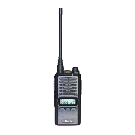
Battery 1 slot charger Antenna Belt clip Hand strap(option) User manual Figure 3-1) XP-400D series main items XP-400D XP-450D XC-100 : Single Slot Desktop Charger XC-200 : Dual Slot Desktop Charger XL-260 : 2,600mAH Li-ion battery pack CP-818X : Ear Speaker... - Page 5 3.1 Appearance of XP-400D Series Radio Figure 3-2) Appearance of XP-400D Series Radio...
-
Page 6: Basic Button Operations
If you press the button shortly, it will operate with the function set by Emergency the YEONHWA M TECH CO.,LTD program, and the default value is Flash Lamp Button set to Emergency. . Press the button long, it is to activate the flash... -
Page 7: Basic Operation
4. Basic operation Please fully read the instruction manual before use. This manual provides important information related to radio operation. 4.1 Installation and Removing the Antenna To install the antenna, insert the antenna into antenna connector and screw the antenna clockwise. To remove the antenna, screw the antenna counter clockwise. -
Page 8: Accessory Connector
Figure 4-2) Installation and Removing the Battery 4.3 Installation and Removing the Belt Clip - To attach belt clip to radio, align belt clip rails with the grooves in radio and slide the belt clip onto the mounting rails until it latches into place. - To remove belt clip from radio, push up on tab of belt clip with flat bladed screw driver and at the same time, slide the belt clip towards the top of Radio figure4-3). -
Page 9: Radio Operation
Figure 4-4) Accessory connector 5. Radio operation The definition of the various buttons of the XP-400D series is the same as Figure 5-1). Figure 5-1) XP-400D Series button definition... -
Page 10: Ptt Button
When you press the NENU / ENTER button, currently programmed menu is displayed and you can select a desired menu using by VOLUME + / LEFT button or VOLUME- / RIGHT button. Figure 5-2) XP-400D Series Menu Figure 5-3) XP-400D Series Menu Tree... -
Page 11: Charging The Battery
6. Charging the Battery 6.1 Safety Notes 1) The radio of XP-400D series receives power from high-performance Li-ion battery (XL-260). XL-260 Battery is safe of high performance and highly reliable, and could be charged very fast. The charging of the enclosed Radio on the other maker’s charger will cause damage on the battery and also, will cause a trouble on the Radio. -
Page 12: How To Charge
Figure 6-1) Battery charging 6.3 How to charge 1) Plug the adapter of the TAD-800L charger in general power AC220V power outlet. 2) When charging the battery that is equipped with radio, please turn off the power of the Radio and plug the Radio in the charger. 3) Even if charging is completed (green lamp lights), please charge more for about 30 minutes for a full charge. -
Page 13: Menu Description
70(W)x104(D)x36(H)m/m Charging current 870mA(Rapid charging) 870mA(Rapid charging) 7. Using the XP-400D Series 7.1 Menu description Press the Menu/OK button on the front to enter the menu mode. In the menu mode, there are eight of the main menus, and set and used according to the application and the environment, it can be more convenient to use. - Page 14 ICON : Individual Contact List (individual Call , Sending individual message) : Group Contact List (Group Call , Sending group message) : All Contact List ( All call, Sending Message to terminal which has same channel and same color) 7.1.2 Message When a new message arrives, the contents will be display on LCD in receive mode.
- Page 15 Outbox It is possible to store up to 10 outbox record and it can see the opponent ID. When outbox is more than 10, the earliest outbox record is cleared first and it is registered. If you want to delete outbox record it can be deleted by selecting delete all menu. 7.1.4 Call Recording This function is used to save the outgoing and incoming calls content.
-
Page 16: Button Lock
This is a feature to encrypt the incoming and outgoing voice. Voice Encryption function can be set for each channel from all of the digital channels. The setting of voice encryption code is using the CPS program, the total number of encryption can be set from 0 to 65535. -
Page 17: Power Save
11. Language The feature is to select the language for the menus. 12. Screen Screen consists of ① Screen1 ② Screen2. 13. Power Save Power save consists of 4 steps: ① OFF ② 1: 1 ③ 1: 2 ④ 1: 4. 7.1.8 Radio Information A menu that shows the information in this device.. - Page 18 8. Precautions Matters affecting the performance of the equipment. Don’t remove the antenna from the Radio or don’t transform the antenna or don’t make any change on the antenna. The strong electronic wave to be emitted from the Radio can have an effect on the performance of the Radio and can cause the Radio to have a defect.
-
Page 19: Safety Notes
In case of the area that medical equipments are being used, please use the Radio after discussion with the equipment maker or the related doctor. Please don’t use the Radio at the place where computer or the other electric/electronic devices are being used, because the strong electronic wave from the Radio can have an effect on the equipments. -
Page 20: Inportant Safety Information
Radios which contains important operating instructions for safe usage and RF energy awareness and control for Compliance with applicable standards and Regulations. For a list of YEONHWA M TECH-approved antennas, batteries, visit the following website: http://www.xradio.co.kr/ Any modification to this device, not expressly authorized by YEONHWA M TECH, may void the user’s authority... -
Page 21: Antenna Specification
Date 2014. 10. 04 Version No. Subject HS10-YH455-WSM Antenna Specification 1.1. General Standard General specification Model name HS10-YH455-WSM Antenna type WHIP Antenna 1.2. Electrical Standard Electrical specification Frequency range 455.0㎒ V.S.W.R 1.9 : 1 Max. Gain(dBi) 1±0.5 Radiation pattern Omni-directional Polarization Vertical Max Power(W) -
Page 22: Warranty Card
2. Warranty is one year from the day the factory. • Failure of the product under normal operating conditions, during the warranty period may be repaired by YeonHwa M Tech Co.,Ltd or our authorized service organization free of charge. 3. For the following cases, some service fees will be charged.
Need help?
Do you have a question about the XP-400D and is the answer not in the manual?
Questions and answers