
Subscribe to Our Youtube Channel
Related Manuals for YEONHWA M TECH XRadio XM Series


Summary of Contents for YEONHWA M TECH XRadio XM Series
- Page 1 USERS MANUAL VHF Transceiver XM-1000 / XM-1200 UHF Transceiver XM-4000 / XM-4200 * Version #1 (2011-05-16) 3F Yukyoung B/D, 544-6, Gasan-dong, Geumcheon-gu, Seoul, 153-803, Korea...
-
Page 2: Table Of Contents
Table of Contents 1. Safety / Warnings 2. Feature 3. Appearance of XM Series Mobile Radio 4. Controls & keys 5. Menu Description 6. Terminal Description 7. Specification... -
Page 3: Safety / Warnings
1. Safety / Warnings Notices ◆ Government law restricts the operation of unlicensed radio transmitters within government controlled territories. ◆ Illegal operation is punishable by fine or imprisonment or both. ◆ Refer service to qualified technicians only. ◆ EXPLOSIVE ATMOSPHERES (GASES, DUST, FUMES, etc.) Shut OFF the transceiver while refueling or while parked in gasoline service stations. - Page 4 Do not transmit with high output power for extended periods; the transceiver may overheat. Do not operate the transceiver when vehicle engine is stopped. The vehicle engine may not be started due to low battery. Do not use incompatible accessories from other manufactures. It could result in damage and or malfunction to the accessory and or to the radio.
- Page 5 RADIO FREQUENCY ENERGY SAFETY INFORMATION Your radio generates RF electromagnetic energy during transmit mode. This radio is designed for and classified as “Occupational Use Only”, meaning it must be used only during the course of employment by individuals aware of the hazards, and the ways to minimize such hazards.
- Page 6 operate the transmitter in areas that are sensitive to electromagnetic radiation such as hospitals, aircraft, and blasting sites. Occupational/Controlled Use The radio transmitter is used in situations in which persons are exposed as consequence of their employment provided those persons are fully aware of the potential for exposure and can exercise control over their exposure.
- Page 7 Installing the transceiver For passenger safety, install the transceiver securely using the supplied mounting bracket and screw set, so the transceiver will not break loose in the event of a collision. 1. Mark the position of the hole in the dash, using the mounting bracket as a template. Using a 4.2mm(5/32 inch) drill bit, drill the holes, then attach the mounting bracket using the supplied screws.
- Page 8 Connecting Microphone 1. Insert the microphone plug into jack on the front panel of the transceiver. Be sure the tab on the microphone plug is facing the left hand side. • 2. Mount the microphone on the microphone hanger where it will be within easy reach of the user 3.
-
Page 9: Feature
2. Feature The XM series Mobile Radio is developed to be user-friendly and compact design, to have various features and to use at the Distribution / industrial / public areas for the safety & convenience of users. The followings are the main features of the XM Series Mobile Radio. 128 x 32 Dots Graphic LCD •... -
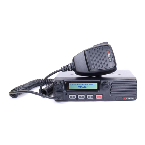
Page 10: Appearance Of Xm Series Mobile Radio
4. Appearance of XM Series Mobile Radio Figure 4-1) Appearance XM-Series Supplied Accessories Item Part Number Quantity ACC-810N : Programming Software(Narrow Band Only – United States Only) ACC-820NW : Programming Software(Narrow and Wide Band – Outside the USA) Acc-8025 : PC Programming Cable(USB) ACC-708 : Mobile Microphone... -
Page 11: Controls & Keys
5. Controls & keys Figure 5-1) XM-1000 / XM-4000 Front panel Figure 5-2) XM-1200 / XM-4200 Front panel Power ON/OFF Volume switch Press and hold the knob over 2 seconds to turn the mobile radio on and off. Rotate to adjust the volume level from 1 to 16. Turn it clockwise to increases the volume and counterclockwise to decreases the volume. - Page 12 Display It is a 125x 36 Graphic type. Each icon indicates related operation. Figure 5-2) XM-Series LCD indicator Selector Rotate to select a channel. Clockwise increase the channel and counterclockwise decrease the channel. Press to select a group if the group is set. Press and hold to enter a menu mode over 2 seconds.
- Page 13 PTT switch To send the signal, press and hold the switch, and then speak into the microphone. Release to receive. 4.1 Programmable key functions Keys can be programmed with the functions listed below. The key can only be programmed with functions, depending on your use intention. Each key has two functions to be programmed, as long press and short press.
- Page 14 Volume adjustment Rotate the volume knob clockwise to increase the volume and counterclockwise to decrease the volume. Maximum increment is 16 levels. Channel selection / Group selection Choose the wanted channel/group using the selector if it is programmed with group. To select a group, push the selector and move to the wanted group.
- Page 15 Scan To activate the Scan function, press the “B” key( at default setting ) or the key programmed as Scan over 2 seconds. The “ “ icon and “ “ icon between Channel No. and Frequency appears on the display. To stop the Scan, press and hold the “B”...
- Page 16 1) Call on selcall ID selection At call waiting, press the “S” key over 2 seconds at default setting or the key programmed as selcall. Rotate the selector to select the selcall channel you want to call. If you want to call “ID: A” in the list, select “A” by the selector. And then push the selector to send the selcall signal to the radio you want to call.
- Page 17 When Stun/Revive function is programmed with selcal ID, stunning a radio or reviving a radio can be activated by remote control. When a radio programmed with Stun ID receives Stun ID from a control radio, all buttons of the programmed radio is locked and out of control. At this status, only PTT works for sending alert sounds.
-
Page 18: Menu Description
5. Menu Description To enter into the menu, press and hold the right knob for 2 seconds. The menu is consisted of 10 main menus and total 29 sub-menus. So, if the menu is set according to circumstance and purpose of use, the radio can be utilized conveniently. The main menu has the list such as SCAN, ID ANI, Message, Pro. - Page 19 ② Push the right knob(Encoder) to set, Back to upper menu. ③ To go to upper menu, press the Red button. 3) Priority List ① The channel list in the group and whether the channel is set as priority or not are displayed as the sign of Yes or No.
- Page 20 ③ To move back to upper menu, press the red button. 2) SELCALL ① Rotate the right knob(Encoder) to select Yes or No. Press the knob to set, back to upper rank. ② ③ To move back to upper menu, press the red button. 5.3 Status setting It is consisted of two kinds like “Send”...
- Page 21 ② To remove the received status, press the “S” button. ③ To erase all of the received status, press the “A” button and select Yes. 5.4 Utility setting There are six sub-menus (RF Power, Lone Worker, Scramble, Lcd Contrast, Big Font, Password).
- Page 22 then press it to set ② To be back to upper menu, press the red button. 4) Big Fong ① Rotate the right knob(Encoder) to select one of them such as “Name, Number, Normal”. And then press it to set. ②...
- Page 23 5.5 Vehicle setting It has two kinds.(Horn Alert, Public AD). Rotate the right knob( Encoder ) to select one of them. And then press the right knob to activate it. 1) Horn Alert ① Rotate the right knob( Encoder) to select “Yes”. And then press the right knob(Encoder) to activate it.
- Page 24 1) ID Sound ① Rotate the right knob( Encoder) to select “Yes”. And then press the right knob(Encoder) to activate it. ② To be back to upper menu, press the red button. 2) Compander ① Rotate the right knob( Encoder) to select “Yes”. And then press the right knob(Encoder) to activate it.
- Page 25 then press it to set. ② To be back to upper menu, press the red button. 7) Call Tone ① Rotate the right knob(Encoder) to select preferred tone. And then press it to set. ② To be back to upper menu, press the red button. 5.7 Repeater/Talk Around It is consisted of 2 kinds sub-menus.(Repeater, Talk Around).
-
Page 26: Terminal Description
② To be back to upper menu, press the red button. 5.8 GPS setting It is consisted of 4 kinds sub-menus.( Method, Interval, Sync Slots, Slot No). Selection is done by the right knob(Encoder). Setting is by pressing the right knob. To send your location data, you must first install a GPS unit onto the transceiver. - Page 27 Output Ground Ground Microphone Jack Pin NO Pin Name Description Specification Remake Backlight of Microphone DC+13.6V DC Power Output 13.8±15% Ground Ground PTT/TXD0 PTT/PC Serial Data 3.3V TTL MIC Ground MIC Ground MIC Signal Input 600Ω HOOK/RXD0 HOOK/PC Serial Data 3.3V TTL MIC Data Detection High Impedance...
-
Page 28: Specification
7. Specification 7.1 XM-1000 / XM-4200 General Frequency Range VHF: 136 ~ 174 MHz Frequency Stability ±1.5PPM (-30 to +60℃) Programmable Channels 256 Channels/32 Group Channel Spacing Dual Channel Spacing 12.5 KHz Dimensions 103mm (H)×52mm (W)×32mm (D) Weight 1.1Kg Power Source DC +13.8 ±15% Current Drain (maximum) Receive mode, rated audio out –... - Page 29 Spurious and Harmonic 70dB FM Hum and Noise 40dB Audio Distortion 3% maximum with 1KHz modulation Audio Frequency Response +1, -3dB from 6dB per octave pre-emphasis Characteristic from 300 ~ 3000Hz Output Impedance 50ohms 7.2 XM-4000 / XM-4200 General Frequency Range XM-4000A / XM-4200A : 400 ~ 475 MHz XM-4000B / XM-4200B : 450 ~ 520 MHz Frequency Stability...
- Page 30 Transmitter RF Power Output 40Watt Spurious and Harmonic 70dB FM Hum and Noise 40dB Audio Distortion 3% maximum with 1KHz modulation Audio Frequency Response +1, -3dB from 6dB per octave pre-emphasis Characteristic from 300 ~ 3000Hz Output Impedance 50 ohms...
Need help?
Do you have a question about the XRadio XM Series and is the answer not in the manual?
Questions and answers