Table of Contents
Advertisement
Quick Links
Advertisement
Table of Contents

Related Manuals for Jet JWBG-8NW


Summary of Contents for Jet JWBG-8NW
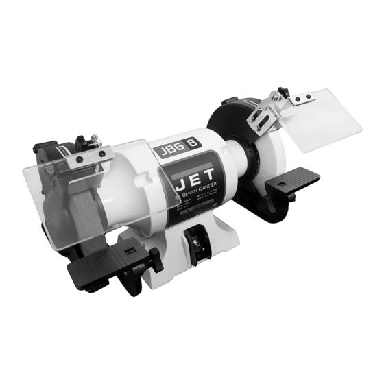
- Page 1 Operating Instructions and Parts Manual 8-inch Bench Grinder Model JWBG-8 (shown with optional grinding wheels – not provided) 427 New Sanford Road LaVergne, Tennessee 37086 Part No. M-726100 Ph.: 800-274-6848 Revision D1 01/2021 www.jettools.com Copyright © 2015 JET...
-
Page 2: Warranty And Service
JET sells through distributors only. The specifications listed in JET printed materials and on official JET website are given as general information and are not binding. JET reserves the right to effect at any time, without prior notice, those alterations to parts, fittings, and accessory equipment which they may deem necessary for any reason whatsoever. -
Page 3: Table Of Contents
2.0 Table of contents Section Page 1.0 Warranty and Service ............................. 2 2.0 Table of contents ............................3 3.0 Safety warnings .............................. 4 4.0 About this machine and manual ........................5 5.0 Specifications ..............................6 6.0 Setup and assembly ............................ -
Page 4: Safety Warnings
Keep children away. Do not use this grinder for other than its 19. Make your workshop child proof with padlocks, intended use. If used for other purposes, JET master switches or by removing starter keys. disclaims any real or implied warranty and holds itself harmless from any injury that may 20. -
Page 5: About This Machine And Manual
The operator is encouraged to familiarize him/herself with ANSI B7.1 – Safety Requirements for Use, Care and Protection of Abrasive Wheels. If there are questions or comments, please contact your local supplier or JET. JET can also be reached at our website: www.jettools.com. -
Page 6: Specifications
Shipping ............................... 52 lb (23.6 kg) The specifications in this manual were current at time of publication, but because of our policy of continuous improvement, JET reserves the right to change specifications at any time and without prior notice, without incurring obligations. -
Page 7: Setup And Assembly
6.0 Setup and assembly 6.1 Shipping contents Carton contents (see Figure 1) Qty. Item Bench grinder (not shown) Spark guard – Left (A) Lock knob (B) Spark guard – Right (C) Eye shield bracket – Left (D) Cross head screw 1/4" x 1/2" (E) Eye shield bracket –... -
Page 8: Mounting The Grinder
6.4 Mounting the grinder The grinder is provided with rubber pads to help prevent movement on a bench. For best results, however, it is recommended the grinder be bolted to the work surface or a grinder stand (fasteners not included). Align mounting holes on grinder with predrilled holes in a bench or grinder stand. -
Page 9: Grinding Wheel Selection
The tool rests must not contact the grinding wheel, Suspend wheel from the hole by a small pin or but should ideally be adjusted to within 1/16” of the finger. wheel, depending upon the type of tool being Gently tap the flat side of the wheel with a non- ground. -
Page 10: Wheel Balancing
6.13 Wheel balancing and repeat the above steps for the outer flange. With the grinder unplugged from the power Continue this combination flange source, and arbor nuts snugged down, rotate movements until the wobble is eliminated. wheels by hand and observe their motion. If required, a shim made of thick paper or card A grinding wheel has proper balance when: stock may be placed between flange and wheel... -
Page 11: Grounding Instructions
7.1 Grounding instructions product will draw. An undersized cord will cause a drop in line voltage resulting in loss of power and 1. All Grounded, Cord-connected Tools: overheating. Table 1 shows correct size to use depending on cord length and nameplate ampere In the event of a malfunction or breakdown, rating. -
Page 12: Tool Rest Adjustment
8.3 Tool rest adjustment paths, and turn on the grinder. Allow it to reach full running speed before beginning operation. As the wheel wears down, the tool rest must be re- Keep a steady, moderate pressure on the adjusted to maintain a 1/16" to 1/8” distance. workpiece and keep it moving at an even pace for Loosen two hex cap screws (H, Figure 8) with smooth grinding. -
Page 13: Cleaning
Note: Turn the locking nut on the right-hand wheel counterclockwise to loosen. Turn the locking nut on the left-hand wheel clockwise to The bench grinder can be mounted to the JET loosen. pedestal stand (optional accessory, p/n 577172), which has an adjustable platform with coolant cup. -
Page 14: Troubleshooting The Jwbg-8
Install new bushings or replace wheel. Excessive vibration. Flanges are worn, bent or have burrs. Inspect flanges, replace if needed. Worn bearings in grinder. Replace bearings. Contact JET Customer Service. Poor quality wheel. Replace wheel with one of better quality. -
Page 15: Replacement Parts
Number of your machine available when you call will allow us to serve you quickly and accurately. Non-proprietary parts, such as fasteners, can be found at local hardware stores, or may be ordered from JET. Some parts are shown for reference only, and may not be available individually. -
Page 16: Jwbg-8 Bench Grinder - Exploded View
13.1.1 JWBG-8 Bench Grinder – Exploded View... -
Page 17: Jwbg-8 Bench Grinder - Parts List
13.1.2 JWBG-8 Bench Grinder – Parts List Index No Part No Description Size 1A ....JWBG8-01A ....Rotor Assembly ..................... 1 1 ....JWBG8-01 ....Arbor ................. 1 (RE: JWBG8-01A) 2 ....JWBG8-02 ....Rotor ................. 1 (RE: JWBG8-01A) 3A .... - Page 18 Index No Part No Description Size 55 ....JBG8A-54 ....Cross Head Screw ........... 1/4 x 1/2 ......2 56 ....6295480 ....Hex Head Screw ............1/4 x 3/8 ......4 57 ....JBG8A-55 ....Eye Shield Bracket – left ................1 58 ....
-
Page 19: Electrical Connections
14.0 Electrical Connections... - Page 20 427 New Sanford Road LaVergne, Tennessee 37086 Phone: 800-274-6848 www.jettools.com...
Need help?
Do you have a question about the JWBG-8NW and is the answer not in the manual?
Questions and answers