Jet JBG Series Operating Instructions And Parts Manual
Hide thumbs
Also See for JBG Series:
- Operating instructions and parts manual (20 pages) ,
- Operating instructions and parts manual (20 pages)
Table of Contents
Advertisement
Advertisement
Table of Contents

Related Manuals for Jet JBG Series


Summary of Contents for Jet JBG Series
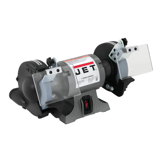
- Page 1 This .pdf document is bookmarked Operating Instructions and Parts Manual JBG Series Bench Grinders Models: JBG-6B, JBG-8B, JBG-10B Model JBG-8B shown 427 New Sanford Road LaVergne, Tennessee 37086 Part No. M-577101-B Ph.: 800-274-6848 Edition 1 05/2018 www.jettools.com Copyright © 2018 JET...
-
Page 2: Important Safety Instructions
Do not use this bench grinder for other than its and replace the guards immediately after intended use. If used for other purposes, JET completion of maintenance. disclaims any real or implied warranty and 19. Check damaged parts. Before further use of... - Page 3 26. Disconnect grinder from power source before 36. Direction of feed: Feed work into a blade or servicing and when changing abrasive wheels. cutter against the direction of rotation of the blade or cutter only. 27. Use recommended accessories. The use of improper accessories may cause risk of injury 37.
-
Page 4: Table Of Contents
14.0 Warranty and Service......................... 20 The specifications in this manual are given as general information and are not binding. JET reserves the right to effect, at any time and without prior notice, changes or alterations to parts, fittings, and accessory... -
Page 5: Introduction
3.0 Introduction This manual is provided by JET covering the safe operation and maintenance procedures for the JET JBG Series Bench Grinders. This manual contains instructions on installation, safety precautions, general operating procedures, maintenance instructions and parts breakdown. This machine has been designed and constructed to provide consistent, long-term operation if used in accordance with instructions set forth in this manual. -
Page 6: Unpacking
5.0 Unpacking Separate all parts from the packing material. Check each part against the Contents of the Shipping Container and make certain that all items are accounted for before discarding any packing material. 5.1 Contents of shipping container Bench Grinder (not shown) Hardware package (contents below) Operating Instructions and Parts Manual Product Registration Card... -
Page 7: Assembly
6.0 Assembly Your bench grinder requires only the assembly of the eye shields and tool rests. For your safety, do not plug the grinder into a power source until all adjustments are complete. An adjustable wrench and a Phillips screwdriver are the only tools you will need to make all normal adjustments and wheel changes on this grinder. -
Page 8: Installing Spark Guard And Eye Shield Mounting Brackets
6.2 Installing Spark Guard and Eye Shield Mounting Brackets Refer to Figure 2: Parts needed: Spark Guard and Eye Shield Brackets assembled from previous page M6 x 12 Hex Cap Screws (E) 6mm Flat Washers (F) 1. Install the left spark guard and mounting bracket (A) to the left wheel housing (M) with two M6 x 12 hex cap screws (E) and two 6mm flat washers (F). -
Page 9: Electrical Connections
If in doubt, use the next heavier The JBG series bench grinders are rated at gage. The smaller the gage number, the heavier 120V, 1PH. These grinders are designed for use the cord. -
Page 10: Operation
8.0 Operation 9.0 Adjustments A bench grinder is designed for hand-grinding 9.1 Eye Shield Tilt Adjustment operations such sharpening chisels, screwdrivers, drill bits, removing excess metal, 1. Loosen lock knob (A , Fig. 3). and smoothing metal surfaces. 2. Adjust eye shield to desired tilt A Medium Grain Abrasive Grinding Wheel is... -
Page 11: User-Maintenance
10.0 User-maintenance other accessory is not recommended and may For safety, turn the switch to OFF and remove result in serious injury! plug from the power source outlet before To change a wheel (refer to Figure 4): adjusting and maintaining the bench grinder. If the power cord is worn, cut or damaged in any 1. -
Page 12: Grinding Wheels
10.4 Grinding Wheels The JET Series bench grinders come equipped with general purpose grinding wheels. Wheels vary according to types of abrasive, hardness, grit size, and structure. JET carries a full line of abrasive grinding, carbide grinding, tool sharpening, and wire wheels. Contact your local distributor for the proper grinding wheel or wire wheel brush for your application. -
Page 13: Troubleshooting Jbg Series Bench Grinders
Undersized extension cord Use correct size extension cord; see manual Short circuit Cord, plug, or motor need repair; call JET Customer Service Dept. Low line voltage Check power line for proper voltage Motor fails to develop full power Faulty motor or capacitor Call JET Customer Service Dept. -
Page 14: Jbg-B Series Grinders - Exploded View
12.1.1 JBG-B Series Grinders – Exploded View... -
Page 15: Jbg-B Series Grinders - Parts List
12.1.2 JBG-B Series Grinders – Parts List Index No Part No Description Size 1 ....JBG6B-001 ....Shaft and Rotor Assembly ............... 1 ....JBG8B-001 ....Shaft and Rotor Assembly ............... 1 ....JBG10B-001 .... Shaft and Rotor Assembly ............... 1 3 .... - Page 16 Index No Part No Description Size 26 ..... TS-1534042 ..... Pan Head Machine Screw (JBG-6B) ....M6x12 ......8 ....TS-1534042 ..... Pan Head Machine Screw (JBG-8B) ....M6x12 ....... 10 ....TS-1534042 ..... Pan Head Machine Screw (JBG-10B) ....M6x12 ....... 10 27 .....
- Page 17 ....JBG10B-059RA ..Eye Shield Assembly Right (#58Thru 60, and #56) ........1 60 ..... JBG6B-060 ....Eye Shield Plate (JBG-6B/8B/10B) ............2 61 ..... JBG6B-061 ....JET-92 Label Base (JBG-6B/8B) ............. 1 ....JBG10B-061 .... JET-113 Label Base (JBG-10B) .............. 1 62 .....
-
Page 18: Electrical Connections - Jbg Series Grinders
13.0 Electrical Connections – JBG Series Grinders... -
Page 20: Warranty And Service
JET sells through distributors only. The specifications listed in JET printed materials and on official JET website are given as general information and are not binding. JET reserves the right to effect at any time, without prior notice, those alterations to parts, fittings, and accessory equipment which they may deem necessary for any reason ®...
Need help?
Do you have a question about the JBG Series and is the answer not in the manual?
Questions and answers