Table of Contents
Advertisement
Advertisement
Table of Contents

Related Manuals for Jet JPSG-618M1


Summary of Contents for Jet JPSG-618M1
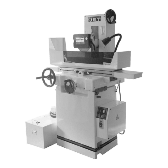
- Page 1 This Manual is Bookmarked Operating Instructions and Parts Manual 6”x18” Precision Manual Surface Grinder Model JPSG-618M1 WMH TOOL GROUP 2420 Vantage Drive Elgin, Illinois 60123 Part No. M-414519 Ph.: 800-274-6848 Revision A 4/05 www.wmhtoolgroup.com Copyright © WMH Tool Group...
-
Page 2: Warranty And Service
This manual has been prepared for the owner and operators of a JET JPSG-618M1 Surface Grinder. Its purpose, aside from machine operation, is to promote safety using accepted operating and maintenance procedures. To obtain maximum life and efficiency from your Surface Grinder and to aid in using it safely, please read this manual thoroughly and follow the instructions carefully. -
Page 3: Table Of Contents
Table of Contents Warranty and Service ...2 Table of Contents ...3 Warning...4 Introduction...6 Specifications ...6 Features of the JPSG-618M1...7 Unpacking ...9 Contents of the Shipping Container ...9 Installation and Assembly ...10 Installing Table...11 Leveling the Machine ...11 Installing Splash Guard ...12 Installing Coolant System ...12... -
Page 4: Warning
Warning 1. Read and understand the entire owners manual before attempting assembly or operation. 2. Read and understand the warnings posted on the machine and in this manual. Failure to comply with all of these warnings may cause serious injury. 3. - Page 5 blahblahblah 20. Make your workshop child proof with padlocks, master switches or by removing starter keys. 21. Give your work undivided attention. Looking around, carrying on a conversation and “horse-play” are careless acts that can result in serious injury. 22. Maintain a balanced stance at all times so that you do not fall or lean against the grinding wheel or other moving parts.
-
Page 6: Introduction
This manual is provided by WMH Tool Group covering the safe operation and maintenance procedures for a JET Model JPSG-618M1 Surface Grinder. This manual contains instructions on installation, safety precautions, general operating procedures, maintenance instructions and parts breakdown. This machine has been designed and constructed to provide years of trouble free operation if used in accordance with instructions set forth in this manual. -
Page 7: Features Of The Jpsg-618M1
Features of the JPSG-618M1... - Page 8 Dimensions and Layout...
-
Page 9: Unpacking
Unpacking Open shipping container and check for shipping damage. Report any damage immediately to your distributor and shipping agent. Do not discard any shipping material until the Surface Grinder is installed and running properly. Compare the contents of your container with the following parts list to make sure all parts are intact. -
Page 10: Installation And Assembly
Installation and Assembly The Surface Grinder should disconnected from power assembly procedures. Refer to parts breakdowns at the end of this manual if clarification is needed for any assembly procedure. 1. Remove the top and sides of the crate. Leave the surface grinder bolted to the pallet until it reaches the desired location. -
Page 11: Installing Table
Installing Table 1. Raise the wheelhead. 2. Clean all rust protected surfaces of the table with kerosene or a light solvent. Do not use gasoline, paint or lacquer thinner, as these will damage painted surfaces. 3. The bearings are in sections and are easily installed with the dovetail connecting ends. -
Page 12: Installing Splash Guard
Installing Splash Guard 1. Attach the splash guard (tall side to the left) to the table, with four phillips pan head machine screws and four flat washers. See Figure 5. The rear splash plate should be secured to the splash guard with wing nuts and flat washers, and the tinted front splash plate should be installed in the tabs at the front of the splash guard. -
Page 13: Removing Wheel Assembly
These last items are optional accessories and can be purchased through your JET dealer. 1. Set the diamond in the overhead dresser, or in the seat on the magnetic chuck. The collar of the dresser is about 5°. -
Page 14: Wheel Balancing
Wheel Balancing 1. Attach the wheel to the surface grinder. 2. Turn on the surface grinder and then turn on coolant flow. 3. Dress the wheel (see instructions above). 4. Remove the dresser, turn off the coolant and dry-run the wheel for ten minutes to remove any coolant. -
Page 15: Extension Cords
Check with a qualified electrician or service personnel if the grounding instructions are not completely understood, or if in doubt as to whether the tool is properly grounded. Repair or replace a damaged or worn cord immediately. Make sure the voltage of your power supply matches the specifications on the motor plate of the Surface Grinder. -
Page 16: Adjustments
Adjustments Timing Belt The timing belt should have 1/2” to 3/4” give with six pounds of pressure applied. The timing belt has been properly tensioned at the factory and should not be adjusted when you receive the machine. As the machine receives use, however, the timing belt may eventually need tightening. -
Page 17: Coolant System
Maintenance Disconnect machine from the power source before doing any maintenance. Failure to comply may cause serious injury. Coolant System Check coolant level once a week. Change coolant after every 100 hours of use, as follows: Remove coolant tank lid, and dispose of the old coolant properly. -
Page 18: Grinding Wheel Selection Chart
Grinding Wheel Selection Chart To obtain an accurate, finished surface the proper grinding wheel must be used. Material to be ground Steel Plate Carbon Steel Carbon Steel Carbon Steel Pipe Forging Carbon Steel Cast Carbon Steel Nickel Chrome Steel Nickel Chrome Molybdenum Alloy Steel Chromium Steel Alloy Steel... -
Page 19: Troubleshooting
Troubleshooting Trouble Probable Cause Excess machine vibration. Frequent wave on the Grinding wheel is not balanced. surface of workpiece. Wheel is too hard. Improper operation. Minor scratch on the surface. Improper dressing of wheel. Improper operation. Burning spots and Improper heat treatment. cracks. -
Page 20: Parts List: Spindle Assembly
Parts List: Spindle Assembly Index No. Part No. Description Size A1 ...618M1-01A1 ... Complete Wheel Assembly ..1 1...SG1202... Balancing Arbor ..1 2...SG1206... Wheel Extractor ..1 3...SG1083... Nut ..1 4...618M-164... Grinding Wheel... 203x31.75x12 mm ... 1 A2 ...618M1-01A2 ... -
Page 21: Spindle Assembly
Spindle Assembly... -
Page 22: Parts List: Column Assembly
Parts List: Saddle and Base Assembly Index No. Part No. C1 ...618M1-03C1 ... Cross Leadscrew Assembly..1 1...618M1-031... Sleeve ..1 2...618M1-032... Bearing Seat..1 3...TS-1502041 ... Socket Head Cap Screw... M5x20 ... 3 4...BB-6202... Bearing... 6202ZZ... 2 5...618M1-035... -
Page 23: Saddle And Base Assembly
Saddle and Base Assembly... - Page 24 Parts List: Column Assembly Index No. Part No. B1 ...618M1-02B1 ... Column and Spindle Seat..1 1...TS-1524041 ... Socket Set Screw ... M8x14 ... 2 2...TS-1523041 ... Socket Set Screw ... M6x12 ... 6 3...618M1-023... Spindle Seat ..1 4...618M1-024...
- Page 25 52 ...618M1-0252... Thrust Needle Bearing ... ASK1730 ... 1 53 ...618M1-0253... Setting Nut... AN04 ... 2 B7 ...618M1-02B7 ... Cross Feed Dial Assembly ..1 54 ...618M1-0254... Index Disc... Inch Style... 1 55 ...618M1-0255... Indicator ..1 56 ...TS-2284102 ... Phillips Pan Head Machine Screw... M4x10 ... 2 B8 ...618M1-02B8 ...
-
Page 26: Column Assembly
Column Assembly... -
Page 27: Parts List: Table Assembly
Parts List: Table Assembly Index No. Part No. D1 ...618M1-04D1 ... Table Assembly ..1 1...TS-1504051 ... Socket Head Cap Screw... M8x25 ... 2 2...TS-1550061 ... Flat Washer ... M8 ... 2 3...618M1-043... Left End Cover..1 4...618M1-044... Table ..1 5...618M1-045... - Page 28 D4 ...618M1-04D4 ... Longitudinal Travel Set ..1 52 ...618M1-0452... Handle... M8x35L ... 2 53 ...618M1-0453... Adjusting Block ..2 54 ...TS-0206022 ... Socket Head Cap Screw... 10-32x1/2'”... 4 55 ...618M1-0455... Square Nut ..4 56 ...TS-1504051 ... Socket Head Cap Screw... M8x25 ... 2 57 ...618M1-0457...
-
Page 29: Table Assembly
Table Assembly... -
Page 30: Parts List: Base Assembly
Parts List: Base Assembly Index No. Part No. Description Size E1...618M1-05E1 ... Base Assembly ..1 1...618M1-051... Base ..1 2...TS-2284101 ... Phillips Pan Head Machine Screw... M4x6 ... 2 3...618M1-053... Base Cover..1 4...TS-2285102 ... Phillips Pan Head Machine Screw... M5x8 ... 4 5...SG1006... -
Page 31: Base Assembly
Base Assembly... -
Page 32: Parts List: Guard And Electrical Assembly
Parts List: Guard and Electrical Assembly Index No. Part No. Description Size F1...618M1-06F1... Splash Guard Set..1 1...618M-212... Wing Nut... DCN5M ... 2 2...TS-1550031 ... Flat Washer ... M5 ... 2 3...SG1119... Rear Splash Plate..1 4...618M1-064... Guard ..1 5...TS-1550041 ... -
Page 33: Guard And Electrical Assembly
Guard and Electrical Assembly... -
Page 34: Parts List: Coolant System
Parts List: Coolant System Index No. Part No. Description Size G1 ...618M1-07G1 ... Coolant System..1 1...618M1-071... Tank ..1 2...618M1-072... Motor Fixed Plate..1 3...TS-1550041 ... Flat Washer ... M6 ... 4 4...TS-1482031 ... Hex Cap Screw... M6x16 ... 4 5...618M1-075... -
Page 35: Coolant System
Coolant System... -
Page 36: Parts List: Electrical Panel
Parts List: Electrical Panel Index No. Part No. Description Size T1...618M1-08T1... Transformer..1 K1M...618M1-08K1M... Magnetic Contactor..1 OL ...618M1-08OL ... Overload..1 F1...618M1-08F1... Low Voltage Fuse ..1 F2...618M1-08F2... Low Voltage Fuse ..1 F3...618M1-08F3... Low Voltage Fuse ..1 F4...618M1-08F4... -
Page 37: Electrical Panel
Electrical Panel DOOR SW... -
Page 38: Electrical Connections
Electrical Connections SPINDEL COOLANT 110V 140V CHUCK POWER... - Page 40 WMH Tool Group 2420 Vantage Drive Elgin, Illinois 60123 Phone: 800-274-6848 www.wmhtoolgroup.com...
Need help?
Do you have a question about the JPSG-618M1 and is the answer not in the manual?
Questions and answers