Table of Contents
Advertisement
Quick Links
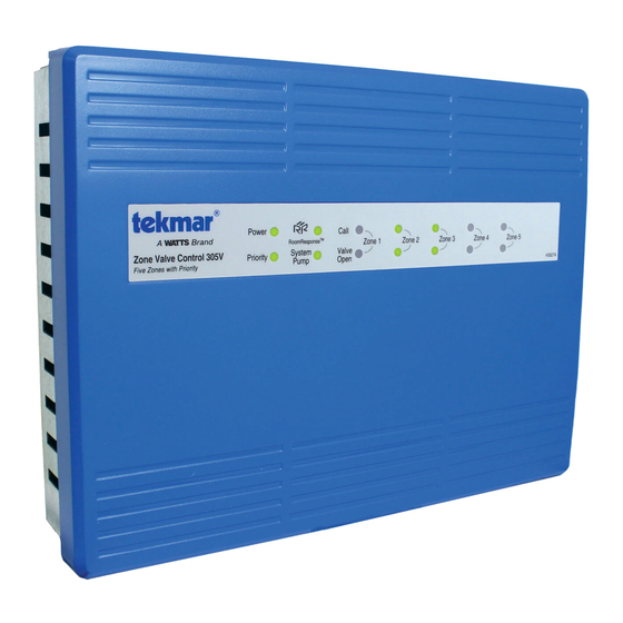
Zone Valve Control 305V
The Zone Valve Control 305V connects up to five thermostats and operates a circulator and zone valves to provide
heating to a zoned hydronic heating system.
Features
• RoomResponse
signal
TM
• Compatible with all low voltage thermostats
• Unlimited zone expansion
• Zone priority
• Priority override
• Pump exercising
• Post purge
• Away signal shared between tekmar thermostats
Zone Valve Control 305V
Five Zones with Priority
• LED for each zone, priority, end switch and
• Four ground screws
• Top, bottom and back conduit knockouts
• Fuses protect transformers and pumps
• Two spare fuses included
• CSA approved
Power
Call
RoomResponse
TM
Zone 1
Zone 2
System
Valve
Priority
Pump
Open
RoomResponse
TM
Zone 3
Zone 4
Zone 5
Installation Manual
H3027A
Advertisement
Table of Contents

Related Manuals for Watts Tekmar 305V


Summary of Contents for Watts Tekmar 305V
- Page 1 Installation Manual Zone Valve Control 305V The Zone Valve Control 305V connects up to five thermostats and operates a circulator and zone valves to provide heating to a zoned hydronic heating system. Features • RoomResponse signal • LED for each zone, priority, end switch and RoomResponse •...
-
Page 2: Table Of Contents
Table of Contents Important Safety Information ......... 2 Application 305V-1 ............. 4 Application 305V-2 ............. 5 Installation ..............3 Application 305V-3 ............. 6 Packaging Contents ........... 3 Tools Required ............3 User Interface ..............7 Materials Required ............. 3 Indicator LED ............. 7 Location .............. -
Page 3: Installation
Radio Frequency Interference The installer must ensure that this control and its wiring off and on, the user is encouraged to try to correct the are isolated and/or shielded from strong sources of interference by re-orientating or relocating the receiving electromagnetic noise. -
Page 4: Application 305V-1
Application 305V-1 The Zone Valve Control 305V operates five heating zones. When the thermostat calls for heat, the zone valve opens, the system pump is turned on and the boiler is fired. Mechanical Legend 305V B1 = Boiler PS = System Pump T1 = WiFi Thermostat 561, 562 or 563 T2, T3 = Thermostat 518 or 519 T4 = Generic Digital Power-Stealing Thermostat... -
Page 5: Application 305V-2
Application 305V-2 The Zone Valve Control 305V operates a four heating zones and a domestic hot water tank. When a thermostat calls for heat, the zone valve opens and the system pump and the boiler turn on once the zone valve end switch closes. The domestic hot water tank is heated using a pump. -
Page 6: Application 305V-3
Application 305V-3 Two Zone Valve Controls operate nine heating zones and a domestic hot water tank. When a thermostat calls for heat, the zone valve opens. The hot water tank is heated using a pump when the tank aquastat calls for heat. The master control operates the system pump and the boiler when there is a call for heat on either the master or member control. Mechanical Legend P1 = Zone 1 DHW Tank Pump T8 = Generic Power-Stealing Thermostat A1 = DHW Tank Aquastat T1 to T4 = WiFi Thermostat 561, 562 or 563 T9 = Generic Bi-Metallic Strip Thermostat B1 = Modulating Condensing Boiler T5, T6 = Thermostat 518 or 519 V1 to V9 = 4-Wire Zone Valves... -
Page 7: User Interface
User Interface - Indicator LED Power Zone 1 Call • On when 115 V (ac) is applied. • On when thermostat 1 calls for heat. • Off when power disconnected or transformer fuse is blown. • Off when thermostat 1 stops calling for heat. Priority Zones 2 to 5 Call •... - Page 8 Expansion Terminals 70 80 • Connect the five wires of the expansion bus from the master to the member controls. Terminal Description A/tN4 Away signal connecting tekmar thermostats RoomResponse signal from member controls Power common Demand signal. 0 Vdc = demand. 2 Vdc = no demand MOD MAX % Priority signal.
- Page 9 Aerco AM Series Camus Modulating MicoFlame – – – – 305V Aerco AM 305V Camus Micoflame • No changes to the boiler are required. • Change control to mode 6 in the control parameters. Bosch Greenstar Heat Transfer Products Elite –...
- Page 10 Laars Mascot FT Peerless Pinnacle PF-200, 210, 300, 399 – – – – – 305V Laars Mascot FT 305V Peerless • No changes to the boiler are required. Peerless Pinnacle Peerless PFA-1 Pinnacle Terminal Interface Adapter Lochinvar Knight Control Strip Board •...
-
Page 11: Technical Data
Raypak XFyre and XPakFT Viessmann Vitodens 200-W, B2HP and Vitocrossal 300 CU3A – – – – 9 10 Viessmann 305V Extension Module EA1 Raypak XFyre or XPakFT 305V Plug 0-10V • Connect to the Viessmann Extension Module EA1 • Set boiler PIM DIP switch 2 to Down. Plug 0-10V. -
Page 12: Limited Warranty And Product Return Procedure
Warranty Limited Warranty The liability of tekmar under this warranty is tekmar Limited Warranty are the Purchaser’s sole responsibility and limited. The Purchaser, by taking receipt of any tekmar product obligation. Purchaser shall indemnify and hold tekmar harmless from (“Product”), acknowledges the terms of the Limited Warranty in and against any and all claims, liabilities and damages of any kind or effect at the time of such Product sale and acknowledges that it nature which arise out of or are related to any such representations or...
Need help?
Do you have a question about the Tekmar 305V and is the answer not in the manual?
Questions and answers