Watts 009 Series Operation, Installation, Maintenance And Repair Manual
Hide thumbs
Also See for 009 Series:
- Installation, maintenance & repair (12 pages) ,
- Installation instructions manual (36 pages) ,
- Instruction, installation, maintenance and repair manual (24 pages)
Table of Contents
Advertisement
Quick Links
Installation, Maintenance, and Repair Manual
Series 009 and LF009
Series 009-FS and LF009-FS
Reduced Pressure Zone Assemblies
Size:
⁄
" – 3"
1
4
WARNING
!
Read this Manual BEFORE using this equipment.
Failure to read and follow all safety and use information
can result in death, serious personal injury, property
damage, or damage to the equipment.
Keep this Manual for future reference.
Local building or plumbing codes may require modifications to the
information provided. You are required to consult the local building
and plumbing codes prior to installation. If this information is not
consistent with local building or plumbing codes, the local codes
should be followed.
Need for Periodic Inspection/Maintenance: This product must
be tested periodically in compliance with local codes, but at least
once per year or more as service conditions warrant.
If installed on a fire suppression system, all mechanical checks,
such as alarms and backflow preventers, should be flow tested and
inspected in accordance with NFPA 13 and/or NFPA 25.
Corrosive water conditions and/or unauthorized adjustments or
repair could render the product ineffective for the service intended.
Regular checking and cleaning of the product's internal components
helps assure maximum life and proper product function.
Installation Instructions
Series 009-FS and LF009-FS assemblies of sizes ½" to 2" are
equipped with an integrated flood sensor that, when activated, trig-
gers notification of potential flood events from excessive relief valve
discharges. An add-on sensor connection kit is required to imple-
ment activation so that the alert system can be used with building
management systems or cellular communication. A retrofit sensor
connection kit is available for existing installations. See "Add-on and
Retrofit Sensor Connection Kits," on pages 6 and 7, for the all
qualifying series models and valve sizes.
Indoors
For indoor installations, the assembly needs to be easily accessible
to facilitate testing and servicing. If it is lo cat ed in a line close to a
wall, be sure the test cocks are easily accessible. A drain line and
air gap should be piped from the relief valve connection as shown
in Figure 1. This is where evidence of discharge is clearly visible,
signaling the need to protect against water damage. Therefore,
never install the assembly in concealed locations. (For more infor-
mation, download the ES-AG/EL/TC specification at watts.com.)
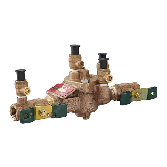
LF009M2-QT-FS
NOTICE
For Australia and New Zealand, line strainers should be installed
between the upstream shutoff valve and the inlet of the backflow
preventer.
Testing
For field testing procedure, refer to Watts installation sheets
IS-TK-DP/DL, IS-TK-9A, IS-TK-99E and IS-TK-99D at watts.com.
For other repair kits and service parts, refer to the Backflow
Prevention Products Repair Kits & Service Parts price list PL-RP-
BPD at watts.com.
For technical assistance, contact your local Watts representative.
Figure 1
Main
Meter
RP/IS-009/009-FS
2
1
⁄
" – 3"
2
Air Gap
Strainer
12"
Advertisement
Table of Contents

Related Manuals for Watts 009 Series


Summary of Contents for Watts 009 Series
- Page 1 Testing If installed on a fire suppression system, all mechanical checks, For field testing procedure, refer to Watts installation sheets such as alarms and backflow preventers, should be flow tested and IS-TK-DP/DL, IS-TK-9A, IS-TK-99E and IS-TK-99D at watts.com.
- Page 2 If flush ing does not clear, remove B. Watts recommends that a strainer be installed ahead of the the first check valve and clean thoroughly. assembly to protect the internal components from unnecessary fouling.
- Page 3 (For more 10 20 30 40 50 60 70 80 90 100 150 Zone Pressure psi information, download Troubleshooting Guide S-TSG at watts.com.) NOTICE Special considerations are necessary when testing as sem ⁄...
- Page 4 Servicing the Relief Valve NOTICE No special tools required to service Series 009 2 " – 3". 1. Remove the four or six relief valve cover bolts while holding the Ball Type Test Cocks cover down. Test Cock No. 4 Second Check Test Cock No.
- Page 5 Servicing First and Second Check Valves 1. Remove the relief valve assembly by following the preceding pro- CHECK ASSEMBLY 1" - 2" cedure. Check Cage Seat 2. Remove the retainer from the body bore. The check valve mod- ules can now be removed from the valve by hand or with a screwdriver.
- Page 6 Watts prod ucts previously or subsequently sold.
- Page 7 Add-on and Retrofit Sensor Connection Kits for Cellular Communication Part Number Add-on/Retrofit Kit Description 88003060 FP-BF-CFS-1/2-2 Includes sensor activation module with cable, deflectors (4), Cellular Gateway with mounting kit, Cellular Sensor Connection Kit ground wire, and power adapter. Use this kit to Series 009-FS, LF009-FS, LFU009-FS, SS009-FS, activate the integrated flood sensor and enable flood U009-FS...
- Page 8 Limited Warranty: Watts Regulator Co. (the “Company”) warrants each product to be free from defects in material and workmanship under normal usage for a period of one year from the date of original shipment. In the event of such defects within the warranty period, the Company will, at its option, replace or recondition the product without charge.
Need help?
Do you have a question about the 009 Series and is the answer not in the manual?
Questions and answers