Table of Contents
Advertisement
Installation & Operation Manual
Boiler Control 256
The Boiler Control 256 is designed to control a single stage heat source in order to provide outdoor reset. The control has a Liquid
Crystal Display (LCD) to view system status and operating information.
Additional functions include:
• Quick Setup for easy installation and programming of control
• User comfort adjustment to increase or decrease building
space temperature
• Advanced settings to fine-tune building requirements
Universal Sensor
Outdoor Sensor
© 2019 tekmar 256 _ D - 09/19
Press & Release:
all 3 buttons, to adjust menu
Press & Hold:
Item, to view settings
, to test.
Boiler Control 256
One Stage Boiler
1
Boil
Input
Included
Input
T I M E
PRGM
Included
Input
tekmar Timer
Optional
• Test sequence to ensure proper boiler operation
• Setback input for energy savings
• CSA C US certified (approved to applicable UL standards)
Power: 24 V ±10% 50/60 Hz
3 VA Class 2
Relay:
240 V (ac) 5 A 1/6 hp
Meets Class B:
Canadian ICES
FCC Part 15
tektra 909-01
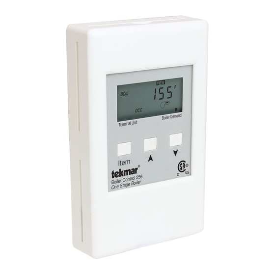
BOIL
F
OCC
Terminal Unit
Boiler Demand
Item
Designed &
Assembled in
Canada
Do not apply power
Signal wiring
2
3
4
5
6 7
must be rated
Out
Com
UnO
Boiler
at least 300V
Sw
T
1
AMPM
2
UNOCC
OVR
S
M
T
W T F
S
Output
8
9
Power
R+
C-
Input
24 V (ac)
Power Supply
Input
Boiler Demand
Signal
Note:
Boiler demand must have
Boiler
an electrical closure
between terminals 7
and 9 before the boiler
is able to fire.
256 _ D
09/19
HVAC Systems Replaces: 06/16
Advertisement
Table of Contents

Related Manuals for Watts Tekmar 256


Summary of Contents for Watts Tekmar 256
- Page 1 AMPM Signal UNOCC W T F Note: Input Output Boiler demand must have tekmar Timer Boiler an electrical closure Optional between terminals 7 and 9 before the boiler is able to fire. © 2019 tekmar 256 _ D - 09/19...
-
Page 2: Table Of Contents
Additional information can be gained by observing the status field and pointers of the LCD. The status field will indicate which of the control’s outputs are currently active. Most symbols in the status field are only visible when the VIEW menu is selected. © 2019 tekmar 256 _ D - 09/19 2 of 20... -
Page 3: Description Of Display Elements
Displays the control operation as indicated by Displays when the control is in occupied (Day) the text. mode. Unoccupied Schedule UNOCC Displays when the control is in unoccupied (Night) mode. © 2019 tekmar 256 _ D - 09/19 3 of 20... -
Page 4: Sequence Of Operation
To reload the factory defaults listed in section B2, power down the control and wait for 10 seconds. Power up the control while simultaneously holding the Item and buttons. The terminal unit number should now be displayed constantly in the LCD rather than flashing. © 2019 tekmar 256 _ D - 09/19 4 of 20... -
Page 5: Section B: Boiler Reset
If a cold outdoor design temperature is selected, the boiler supply temperature rises gradually as the outdoor temperature drops. If a warm outdoor design temperature is selected, the boiler supply temperature rises rapidly as the outdoor temperature drops. © 2019 tekmar 256 _ D - 09/19 5 of 20... - Page 6 The amount of natural convection to the space is dependent on the supply water temperature to the heating element and the room air temperature. Default values: BOIL DSGN = 180°F (82°C), BOIL MIN = 140°F (60°C) © 2019 tekmar 256 _ D - 09/19 6 of 20...
- Page 7 If the installed boiler is designed for low temperature (10) 80 °F operation, set the BOIL MIN adjustment to OFF. (27°C) (16) (-7) (-18) (-29) Outdoor Air Temperature © 2019 tekmar 256 _ D - 09/19 7 of 20...
-
Page 8: Installation
Manual D 256, Application Brochure A 256. Note: Carefully read the details of the Sequence of Operation to ensure that you have chosen the proper control for your application. © 2019 tekmar 256 _ D - 09/19 8 of 20... - Page 9 Power must not be applied to any of the wires during the rough-in wiring stage. Install the Outdoor Sensor and Universal Sensor according to the directions on the following page. © 2019 tekmar 256 _ D - 09/19 9 of 20...
- Page 10 • Replace the cover of the sensor enclosure. • Connect the 2 wires from the outdoor sensor to the Out and Com terminals on the 256 (2 and 3). © 2019 tekmar 256 _ D - 09/19 10 of 20...
- Page 11 The two wires from the sensor are connected to the terminal block provided in the enclosure. The other side of the terminal block is used to connect wires from the control. Bottom of Enclosure 080 Universal Cable Tie Sensor © 2019 tekmar 256 _ D - 09/19 11 of 20...
- Page 12 1,172 196,358 22,763 4,184 1,073 165,180 19,900 3,760 139,403 17,436 3,383 118,018 15,311 3,050 100,221 13,474 2,754 85,362 11,883 2,490 72,918 10,501 2,255 62,465 9,299 2,045 53,658 8,250 1,857 © 2019 tekmar 256 _ D - 09/19 12 of 20...
- Page 13 If the boiler does not turn on, refer to any installation or troubleshooting information supplied with the boiler. (The boiler may have a flow switch that prevents firing until the boiler loop pump is running). If the boiler operates properly, remove power from the boiler circuit. © 2019 tekmar 256 _ D - 09/19 13 of 20...
- Page 14 If an external timer (tekmar Timer 033) or switch is used, connect the two wires from the external switch to the Com and UnO Sw terminals (3 and 4). When these two terminals are shorted together, the control registers an unoccupied signal. Timer switch © 2019 tekmar 256 _ D - 09/19 14 of 20...
-
Page 15: Dip Switch Setting
To exit the ADJUST menu, press and release the Item button to advance to the ESC item. Then either press button, or leave the buttons alone for 20 seconds. © 2019 tekmar 256 _ D - 09/19 15 of 20... -
Page 16: Control Settings
(2 to 38°C) INDR DSGN ADJUST F ° BOIL The design supply water temperature used in the 70 to 220°F heat loss calculation for the heating system. (21 to 109°C) © 2019 tekmar 256 _ D - 09/19 16 of 20... - Page 17 The units of measure that all of the temperatures °F, °C are to be displayed in the control. ADJUST This item exits the ADJUST menu by pressing either the button. © 2019 tekmar 256 _ D - 09/19 17 of 20...
-
Page 18: Testing And Troubleshooting
Sensors in the Testing the Wiring section to simulate closed contacts on the terminal blocks as required. Test the sensors and their wiring as described in the Testing section. © 2019 tekmar 256 _ D - 09/19 18 of 20... -
Page 19: Error Messages
— 3/8” OD x 3/4” (9.5 OD x 19 mm) Approvals — CSA C US, UL listed Operating range — -60 to 255°F (-50 to 125°C) Sensor — NTC thermistor, 10 kΩ @ 77°F (25°C ±0.2°C), ß=3892 © 2019 tekmar 256 _ D - 09/19 19 of 20... -
Page 20: Technical Data
WARNING: This product contains chemicals known to the State of California to cause cancer and birth defects or other reproductive harm. For more information: Watts.com/prop65 All specifications are subject to change without notice Tel: (250) 545-7749 • Fax: (250) 984-0815 tekmarControls.com...
Need help?
Do you have a question about the Tekmar 256 and is the answer not in the manual?
Questions and answers