Advertisement
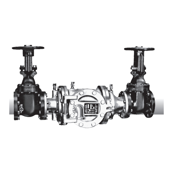
Series 900
Reduced Pressure Principle Backflow Preventers
1
Sizes: 2
/
", 6" (65, 150mm)
2
• Service
• Replacement Parts
• Maintenance
For field testing procedure, send for IS-TK-DP and S-FT-TK9A.
For troubleshooting guide, send for S-TSG.
For other repair kits and service parts, send for PL-RP-BPD.
For technical assistance, contact your local Watts
representative. See back page.
Attn. Installer: After installation please leave this instruction
sheet for occupant's information.
Important: Inquire with governing authorities for local installa-
tion requirements.
Note: For Australia and New Zealand, line strainers should be
installed between the upstream shutoff valve and the inlet of the
backfl ow preventer.
Watts product specifi cations in U.S. customary units and
metric are approximate and are provided for reference only.
For precise measurements, please contact Watts Technical
Service. Watts reserves the right to change or modify prod-
uct design, construction, specifi cations, or materials without
prior notice and without incurring any obligation to make such
changes and modifi cations on Watts products previously or
subsequently sold.
RP-L900
Advertisement
Table of Contents

Related Manuals for Watts 900 Series


Summary of Contents for Watts 900 Series
- Page 1 For precise measurements, please contact Watts Technical Service. Watts reserves the right to change or modify prod- uct design, construction, specifi cations, or materials without prior notice and without incurring any obligation to make such changes and modifi...
- Page 2 Service Replacement Parts and Maintenance Series 900 2nd Check Valve DISC MAINTENANCE 1st Check Valve TOOLS Required for 4" and 6" only. G. If damage or deterioration to either seat is evident, remove the eight socket head screws and remove seat and gasket from valve.
- Page 3 Cauti o n: Do not over-tighten the wing nut as this may dam- Q. After disassembly and cleaning, reassemble the check valve age the relief valve disc. module in the position shown in photo (B). R. Inspect access door O-ring seal to be sure it is in its proper K.
- Page 4 Silicone Grease Limited Warranty: Watts Regulator Co. (the “Company”) warrants each product to be free from defects in material and workmanship under normal usage for a period of one year from the date of original shipment. In the event of such defects within the warranty period, the Company will, at its option, replace or recondition the product without charge.
Need help?
Do you have a question about the 900 Series and is the answer not in the manual?
Questions and answers