
Related Manuals for BCM AR6MXCS-DEV


Summary of Contents for BCM AR6MXCS-DEV
- Page 1 AR6MXCS- Series Quick Start Guide Ver 0.1 This Quick Start Guide is for BCM AR6MXCS ARM motherboards based on Freescale i.MX6 Cortex A9 platform.
- Page 2 Contents 1. Overview…………………………………………………….3 2. Mainboard Illustration…………………………………….4 3. Getting Started……………………………………………..5 4. Jumper and Connector pin out………………………….6 AR6MXCS Quick Start Guide Page 2...
-
Page 3: Overview
1. Overview The AR6MXCS is a simplified version of our popular AR6MX platform. The AR6MXCS features a Single-Core i.MX6 processor from Freescale. The hardware specifications for the AR6MXCS board are the following: o Single-Core ARM® Cortex A9 processor at 1GHz o 512MB of 32-bit DDR3 Memory @400Mhz o LVDS Outputs for 1080p displays o HDMI 1.4a... -
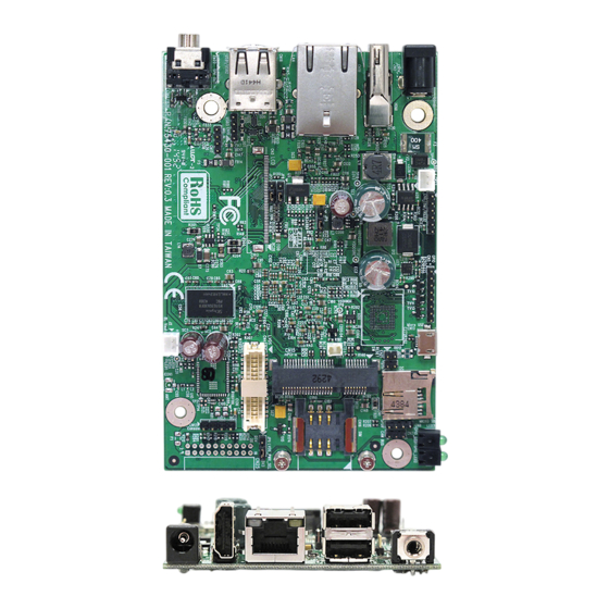
Page 4: Mainboard Illustration
2. Mainboard illustration: Locations of IO ports & Jumper settings definition Board Top View: Board Side View: AR6MXCS Quick Start Guide Page 4... -
Page 5: Getting Started
3. Getting Started 1.1 Connect a HDMI monitor to CN2 (HDMI). 1.2 Connect a USB mouse/keyboard either to the rear I/O USB connectors (CN18), or through the onboard header CN10 (USB cable not included) 1.3 Connect the 5V power adapter to CN14 1.4 Plug in the power adapter to an outlet and the board will boot up 1.5 Connect TTL Console to CN12. -
Page 6: Jumper And Connector Pin Out
4. Jumper Settings and Pin Definition CN1: Micro SD Card Socket Connector type:HDR 1X3 2.0mm Definition Definition Definition DATA2 DAT0 L0_PWR CD/DATA3 DAT1 D3V3 Default Jumper selector LVDS0 PWR SEL 1 - 2 2 - 3 3.3V CN2:HDMI Conn Connector type:HDMI Definition Definition D2_SHIELD... - Page 7 LVD 0_CLK_P LVDS0_TX0_N LBL0_PWM LV S0_TH_SCL LVDS0_CLK_N LVDS0_TX1_P LVDS0_TH_SDA LCD0_PWR LVDS0_TX1_N LCD0_PWR CN5:GPIO CN6:COM-1 RS232 Connector type:HDR 1x8 2.0 Connector type:1x6 2.00mm DIP Definition Definition GPIO1 SOUT GPIO2 GPIO3 GPIO4 GPIO5 GPIO6 GPIO7 GPIO8 CN7:CAN BUS CN8:SPDIF Connector type:HDR 1x3 2.0 Connector type:HDR 1x4 2.0 Definition Definition...
- Page 8 CON_RXD AD_AGND CN18:USB-1/USB-2’ CN19:LAN Conn’ Connector type:USAF-8D-HNR0SPJ Connector type:RTA-164AAK1A Definition Definition Definition Definition USBV1 USBV2 GE_MDI0+ GE_MDI3+ USB1P- USB2P- GE_MDI0- GE_MDI3- USB1P+ USB2P+ GE_MDI1+ LED2 GE_MDI1- D3V3 D3V3 LED1 GE_MDI2+ GE_MDI2- CN16:SIM Card Slot CN20:I2C3 Connector type:SIM_Socket Connector type:Header 1x2 2.0 Definition Definition SIM_VCC...
- Page 9 Connector Type: Header 1x2 2.0 Definition CN15:mPCI-e Port 1 Connector type:PCI-e_MINI_CARD Definition Definition Definition Definition WAKE# UIN_VPP PET_N0 LED_WPAN# +3.3V_1 UIN_GND SMB_DATA RSVD10 RSVD1 GND8 PET_P0 +1.5V_3 GND7 UIN_IN GND10 RSVD11 RSVD2 RSVD18 GND6 GND12 +1.5V_1 GND3 USB_D- RSVD12 CLKREQ# PERST# RSVD5 +3.3V_2...
Need help?
Do you have a question about the AR6MXCS-DEV and is the answer not in the manual?
Questions and answers