Table of Contents
Advertisement
Quick Links
Advertisement
Table of Contents

Subscribe to Our Youtube Channel
Related Manuals for Member's Mark GR2071001-MM-00


Summary of Contents for Member's Mark GR2071001-MM-00
- Page 1 EXHIBIT Q-3 M. HERMES DECLARATION...
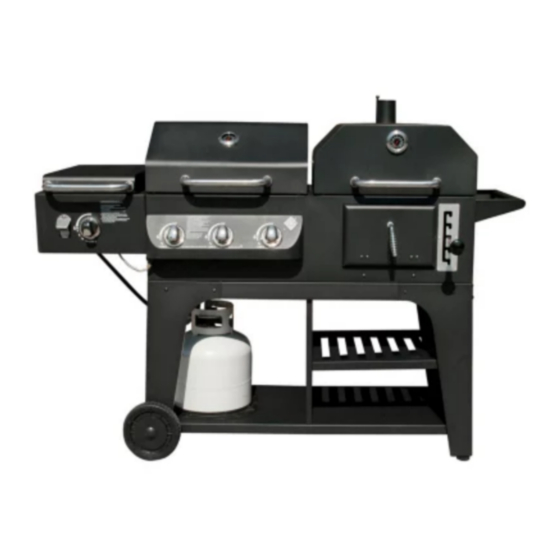
- Page 2 Hybrid Grill Infrared, Gas & Charcoal Cooking System Models Number: GR2071001-MM-00 ASSEMBLY & OPERATING INSTRUCTIONS For Outdoor Use Only This instruction manual contains important information necessary for the proper assembly and safe use of the appliance. Read and follow all warnings and instructions before assembling/using the appliance.
-
Page 3: Safety Labels
DANGER If you smell gas: 1. Shut off gas to the appliance. 2. Extinguish any open flame. 3. Open lid. 4. If odor continues, keep away from the appliance and immediately call your gas supplier or fire department WARNING 1. Do not store or use gasoline or other flammable liquids or vapors in the vicinity of this or any other appliance. - Page 4 GAS GRILL GENERAL WARNINGS WARNING This outdoor cooking gas appliance shall be used only outdoors and shall not be used in a building, garage or any other enclosed area. This outdoor cooking gas appliance is not intended to be installed in or on boats. This appliance is not intended to be installed in or on recreational vehicles.
-
Page 5: Lp Gas Cylinder
USE OF LP GAS CYLINDER AND INSTALLATION BEFORE INSTALLING: The installation must conform with local codes or, in the absence of local codes, with either the National Fuel Gas Code, ANSI Z223.1/NFPA 54, Natural Gas and Propane Installation Code, CSA B149.1, or Propane Storage and Handling Code, B149.2,or the Standard for Recreational Vehicles, ANSI A 119.2/NFPA 1192, and CSA Z240 RV Series, Recreational Vehicle Code, as applicable. - Page 6 WARNING Place dust cap on cylinder valve outlet whenever the cylinder is not in use. Only install the type of dust cap on the cylinder valve outlet that is provided with the cylinder valve. Other types of caps or plugs may result in leakage of propane. DANGER DO NOT connect this grill to an existing #510 POL cylinder valve with Left hand threads.
-
Page 7: Installing Gas Cylinder
INSTALLING GAS CYLINDER Check that cylinder valve is closed by turning knob clockwise. Place cylinder to cylinder fixture which Cylinder is at the bottom cart of the grill per picture shown. Cylinder WARNING: Keep the fuel supply hose Fixture away from any heated surfaces. WARNING The pressure regulator and hose assembly supplied with your gas grill must be used. - Page 8 Turn the burner valves off. Turn the tank valve off fully (turn clockwise to stop). Detach the regulator assembly from the tank valve by turning the quick coupling nut counterclockwise. LEAK TEST WARNING DO NOT SMOKE WHILE CONDUCTING LEAK TEST. NEVER PERFORM LEAK TEST WITH AN OPEN FLAME.
-
Page 9: Lighting Instructions
LIGHTING INSTRUCTIONS BEFORE LIGHTING WARNING Inspect the gas supply hose prior to turning the gas “ON”. If there is evidence of cuts, wear, or abrasion, it must be replaced prior to use. Do not use the grill if the odor of gas is present. Only the pressure regulator and hose assembly supplied with the unit should be used. - Page 10 LIGHTING THE SIDE BURNER (Side burner): DANGER Never close the SIDE BURNER LID during operation 1. Read all instructions before lighting. 2. Open lid during lighting. 3. Push and turn main burner knob slowly to HI. The side burner should light immediately. 4.
-
Page 11: Flame Characteristics
DANGER Keep your face and hands as far away from the grill as possible when lighting it. FLAME CHARACTERISTICS This procedure outlines how to check for proper burner flame characteristics. Burner flames should be blue and stable with little yellow tips, with no excessive noise, or lifting. - Page 12 You should inspect the burners at least once a year or immediately after any of the following conditions occur: The smell of gas in conjunction with the burner flames appearing yellow. The grill does not reach temperature. The grill heats unevenly. The burners make popping noises.
- Page 13 When an appliance is supplied on casters and is connected to the supply piping by means of a connector for movable appliances, the operator shall be aware there is a restraint on the appliance and, if disconnection of the restraint is necessary, to reconnect this restraint after the appliance has been returned to its originally installed position.
-
Page 14: Charcoal Grill General Warnings
CHARCOAL GRILL GENERAL WARNINGS WARNING The maximum weight of charcoal to be used is 3.3lb (1.5kg). Too much charcoal may cause the gas component to over heat and malfunction. The charcoal chamber is for charcoal cooking only. Gas grill and side burner cannot be used for charcoal cooking. -
Page 15: Preparation For Use & Lighting Instructions
distance from hot steam and flame flare-ups. Extinguished coals and ashes should be placed a safe distance from all structures and combustible materials. Never raise or lower charcoal grate when water is smoking as hot water may splash onto coals. Use caution since flames can flare-up when fresh air suddenly comes in contact with fire. - Page 16 IF USING CHARCOAL CHIMNEY STARTER, PROCEED TO STEP 5. If you choose to use charcoal lighting fluid, ONLY use charcoal lighting fluid approved for lighting charcoal. Do not use gasoline, kerosene, alcohol or other flammable material for lighting charcoal. Follow all manufacturer’s warnings and instructions regarding the use of their product. Start with 3.3 lb(1.5 kg ) of charcoal.
- Page 17 Grilling/Searing Step 1 Follow the instructions below carefully to build a fire. You may use charcoal and/or wood as fuel in the charcoal side of the Hybrid Grill (see “Adding Charcoal/Wood During Cooking” section of this manual). WARNING Use only a high grade plain charcoal or charcoal/wood mixture. If using a Charcoal Chimney Starter, follow “Operating Instruction Step 4”...
-
Page 18: Flavoring Wood
Step 5 Place food on cooking grates and close grill lid. Always use a meat thermometer to ensure food is fully cooked before removing from grill. Step 6 Allow grill to cool completely, and then follow instructions in the “After-Use Safety” and “Proper Care &... -
Page 19: Adding Charcoal/Wood During Cooking
Adding Charcoal/Wood During Cooking Additional charcoal and/or wood may be required to maintain or increase cooking temperature. Step 1 Stand back and carefully open grill lid. Use caution since flames can flare-up when fresh air suddenly comes in contact with fire. Step 2 Wearing oven mitts/gloves, use charcoal tray adjuster to place charcoal tray at the lowest level of cooking chamber. -
Page 20: Proper Care And Maintenance
Proper Care & Maintenance Cure your grill periodically throughout the year to protect against excessive rust. To protect your grill from excessive rust, the unit must be properly cured and covered at all times when not in use. Wash cooking grates with hot, soapy water, rinse well and dry. Lightly coat grates with vegetable oil or vegetable oil spray. -
Page 21: Packing List
Packing List ATTENTION Please do not withdraw all small parts from the packing boxes immediately Each assembly step in this instruction manual has shown how can you find the particular part(s) from the packing box quickly. We strongly recommend that you read through the assembly procedure before proceeding assembly. - Page 22 Box D Box A Part 17 Left Pivot Leg Part 1 Chimney Cover Part 18 Right Pivot Leg Part 5 Air Vent Part 33 Left Wheel Leg Part 7 Bezel 6pcs Part 34 Right Wheel Leg Part 9 Charcoal Door Handle Part 19 Leg Adjuster 2pcs...
-
Page 23: Product Diagram
Product diagram 22 of 47 20121224-Ver1... -
Page 24: Component List
Component List 3.Right Lid 1.Chimney Lid 2.Charcoal Chimney 4.Grill Body (Charcoal) Box D Qty: 1 pc Box C Qty: 1 pc Qty: 1 pc Qty: 1 pc 5.Air Vent 6.Grill Handle 7.Bezel 8. Lid Handle Box D Qty: 1 pc Box C Qty: 1 pc Box D... -
Page 25: Hardware List
21.Left Lid (Gas) 22.Side Burner 23.Side Burner 24.Side Burner Cooking Grate Control Panel Qty : 1 pc Box E Qty: 1 pc Box B Qty: 1 pc Box F Qty: 1 pc 25.Bottle Opener 26.Control Knob 27.Side Burner 28. Side Burner Bracket (Left) Bracket (Right) Box D... - Page 26 Item No. Item name Diagram M6 X 12mm Bolt (Black) M12 Washer Plastic Rivet M6 X 15mm Bolt (Black) M10 Locking Nut M10 Washer Cotter Pin M6 Locking Nut M6 X 12mm Bolt (Sliver) M6 X 12mm Hexagonal Bolt 25 of 47 20121224-Ver1...
- Page 27 Hardware List M6 X 35mm Bolt (Black) M8 Cap Nut Spring Hinge Pin Screwdriver Hex Nut Wrench 26 of 47 20121224-Ver1...
-
Page 28: Assembly Procedures
Assembly Procedures Step 1: Attach the Leg Brace (16) to the Left Wheel Leg(33) and Right Wheel Leg(34) by using 4 pcs of Bolts (A). Tips. Each “Wheel Leg” has a hole at the bottom. (Please see the triangles) Step 2: Attach the Leg Brace (16) to the Left Pivot Leg(17) and Right Pivot Leg(18) by using 4 pcs of Bolts (A). Screw in the Leg Adjuster(19) to each Pivot Leg. - Page 29 Step 3: Place the legs on the floor in upward position as shown. Attach the 2 pcs of Middle Brace(15) by using 8 pcs of Bolt (A) Tips. Make sure the middle bracket must be on top during the assembly and pointing inward or pointing inside. (Please see the triangles) Step 4: Attach the Bottom Shelf(20) to the Legs assembly by using 4 pcs of Bolts (A) Tips: Make sure the big tank hole of bottom shelf should be placed at the side of WHEEL leg opposite the leg adjustor.
- Page 30 Step 5: Attach the 2 pcs of Wheel(35) to wheel leg sides by using 2 pcs of Wheel Washer(B) and Wheel Axle(36). The Wheel Axle can be fastened by the Hex Nut Wrench(P). Attach the Wheel Cover (37) to the wheels. Step 6: Attach the Middle Panel(39) to the bottom cart by using 4pcs of Bolts(A).
- Page 31 Step 7: Attach the Bottom Rack(14) to the bottom cart by using 2 pcs of Bolt(A). Tip: Attach the bottom rack to bracket first per (a), the fasten the bolts per (b). (Please see the Gray Triangles). Step 8: Attach the Tank Fixture(38) to the big hole of bottom cart by snapping in with 3 pcs of Plastics Rivet (C). 30 of 47 20121224-Ver1...
- Page 32 Step 9: This step requires 2 people! Attach the Grill Body(4) on the bottom cart by using 6 pcs of Bolt(D) . Tips: Do not tighten all the screws during installing each bolt. Make sure the grill body should be well aligned with the bottom cart braces then tighten all bolts.
- Page 33 Step 11: Attach the Air Vent(5) to the charcoal side of grill body by using 1pc of Bolt(A) and Nut(H). Step 12: Attach the Charcoal Grate Lifter(10) to the charcoal side of grill body. Secure the lifter by using 1 pc of Cotter Pin (G).
- Page 34 Step13: Attach Left and Right Side Burner Bracket (27 and 28) to the grill body by using 2 pcs of Bolt(A). Step14: Attach the Side Burner(22) on the side burner brackets per following shown. 33 of 47 20121224-Ver1...
- Page 35 Step15: Secure the side burner by using 2pcs of Bolt(A). Step16: Attach the Bottle Opener (25) to the Side Burner Control Panel(24) by using 2 pcs of Bolt (I). 34 of 47 20121224-Ver1...
- Page 36 Step 17. Take out the Side valve with gas regulator assembly from main control panel at grill side per following shown. Understand the construction of side burner gas components, it would help you proceed the side burner assembly in next several steps.
- Page 37 ATTENTION: DO NOT OVER TWISTING THE FLEXIBLE STAINLESS GAS TUBE Step 18: GENTLY bend the Flexible Stainless Gas Tube its route is similar to illustration (a). Loosen the pre-assembled screws at Side Burner Gas Valve per illustration (b) Tips: Do not let the pre-assembled screws get grid of the gas valve per (c). It will help to proceed next step. 36 of 47 20121224-Ver1...
- Page 38 Step 19: Attach the Side Burner Gas Valve to Side Burner Control Panel per illustration (a) and (b). Before fastening the pre-assembled screws of gas valve, make sure the gas valve should be slipped up at correct position per illustration (c). 37 of 47 20121224-Ver1...
- Page 39 Step20: Connect the Ignition Wire with Ignition Wire Junction first. Attach the Side Burner Control Panel to the Control Panel Bracket. During putting the control panel on the bracket, make sure the Valve Nozzle should be engaged with the Gas Valve Inlet Hole and Side Burner Venturi. 38 of 47 20121224-Ver1...
- Page 40 Step 21: Attach the side burner control panel to the side burner per shown. Secure the side burner control panel by using 2 pcs of Bolt (A). Tips: Before secure the side burner control panel. Double check following points: (1) Make sure the Gas Valve Nozzle has already engaged with the Side Burner Venturi. You can see and check through the observation hole at side burner bracket.
- Page 41 Step 23: Attach the Grill Handle (6) to the grill body by using 4 pcs of Hexagonal Bolt(J). These bolts can be fastened by Wrench (P). Step 24: Attach the Lid Handle(8) and Bezel(7) to the side burner lid by using 2 pcs of Bolt(D) 40 of 47 20121224-Ver1...
- Page 42 Step 25: Attach the Lid Handle(8) and Bezel(7) to Right Lid(3) and Left Lid (21) by using 4 pcs of Bolt(D) respectively. Attach the Upper Hinge (41) to the Right Lid(3) and Left Lid(21)by using 8 pcs of Bolt(K) respectively. Tips: Make sure use the correct hinges for this step.
- Page 43 Step27: Attach the Lower Hinge(42) to the back of grill body by using 8pcs of Bolt(K). Tips: Make sure use the correct hinges for this step. Step 28: Attach the Right and Left Lid on the grill body. The hinges are secured by using 4pcs of Hinge Pin(N) and Cotter Pin(G) per following shown.
- Page 44 Step 29: Put the Frame Tamer (13) over the gas burners first. Then put Side Burner Cooking Grate(23), Gas Grill Cooking Grate(32) and Charcoal Grill Cooking Grate(12) to the grill body. The Cooking Grate Lifter(31) is for lifting up the cooking grates during the cooking. Step 30: Attach the Warming Rack(11) to the grill chambers.
- Page 45 Step31: Take out the grease tray from the grill body. Attach Charcoal Grease Tray Handle(29) by using 2 pcs Bolt(A). Also put the Grease Cup(30) to the Grill body per shown. Assembly Completed 44 of 47 20121224-Ver1...
-
Page 46: Troubleshooting
Troubleshooting Problem Possible Cause Prevention / Cure Burner will not light using “Ignition Wire/or electrode covered with Clean wire and/or electrode, with Burner” cooking residue. rubbing alcohol. Electrode and burner are wet. Wipe dry with cloth Electrode cracked or broken – Call customer Service to replace sparks at crack electrode... -
Page 47: Limited Warranty
Flashback (Fire in burner tube) Burner and/or burner tubes Clean burner and/or burner tubes. Grill too hot Excess grease build-up causing Clean grill grease fire. Control knob is too hot Excess grease build-up causing Clean Grill grease fire. Check gas component Wrong connection of gas connection per this manual at component... - Page 48 IF CUSTOMER SERVICE BECOME NECESSARY: The Original Purchaser is responsible for shipping and handling charges of the returned item(s) and replacement parts, if any. All parts to be replaced will need to be shipped before replacement items will be sent. Follow the Customer Service Representative’s instructions exactly.
Need help?
Do you have a question about the GR2071001-MM-00 and is the answer not in the manual?
Questions and answers