Table of Contents
Advertisement
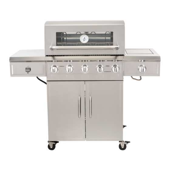
5 Burner Gas Grill
OWNER'S MANUAL
ASSEMBLY AND OPERATING IN STRUC TIONS
SAVE THIS MANUAL FOR FUTURE REFERENCE
Model GAS0565AS / GAS0565ASO
WARNING
NOTICE TO INSTALLER:
HAZARDOUS EXPLOSION MAY RESULT IF THESE WARNINGS
LEAVE THESE INSTRUCTIONS WITH
AND INSTRUCTIONS ARE IGNORED. READ AND FOLLOW ALL
THE GRILL OWNER FOR FUTURE
WARNINGS AND INSTRUCTIONS IN THIS MANUAL TO AVOID
REFERENCE .
PERSONAL INJURY, INCLUDING DEATH OR PROPERTY DAMAGE.
Advertisement
Table of Contents

Subscribe to Our Youtube Channel
Related Manuals for Member's Mark GAS0565AS


Summary of Contents for Member's Mark GAS0565AS
- Page 1 5 Burner Gas Grill OWNER’S MANUAL ASSEMBLY AND OPERATING IN STRUC TIONS SAVE THIS MANUAL FOR FUTURE REFERENCE Model GAS0565AS / GAS0565ASO WARNING NOTICE TO INSTALLER: HAZARDOUS EXPLOSION MAY RESULT IF THESE WARNINGS LEAVE THESE INSTRUCTIONS WITH AND INSTRUCTIONS ARE IGNORED. READ AND FOLLOW ALL...
- Page 2 IMPORTANT SAFETY WARNINGS WE WANT YOU TO ASSEMBLE AND USE YOUR GRILL AS SAFELY AS POSSIBLE. THE PURPOSE OF THIS SAFETY ALERT SYMBOL IS TO ATTRACT YOUR ATTENTION TO POSSIBLE HAZARDS AS YOU ASSEMBLE AND USE YOUR GRILL. WHEN YOU SEE THE SAFETY ALERT SYMBOL PAY CLOSE ATTENTION TO THE INFORMATION WHICH FOLLOWS! READ ALL SAFETY WARNINGS AND INSTRUCTIONS CAREFULLY BEFORE ASSEMBLING AND OPERATING YOUR GRILL.
-
Page 3: Table Of Contents
TABLE OF CONTENTS: General Warnings ..........3-4 LP Gas Cylinder (Tank) Specifi cations and Installation . -
Page 4: General Warnings
GENERAL WARNINGS: WARNING • Leak test all connections before fi rst use, even if grill was purchased fully assembled and after each tank refi ll. Check the propane tank rubber seal for damage. • Always check the grill and propane tank prior to each use as indicated in the “Checking for Leaks” & “Pre-Start Check List”... -
Page 5: Lp Gas Cylinder (Tank) Specifications And Installation
• Grill is hot when in use. To avoid burns: • DO NOT attempt to move the grill. • Block the wheels so the unit does not accidentally move. • Wear protective gloves or oven mitts. • DO NOT touch any hot grill surfaces. •... - Page 6 LP GAS CYLINDER (TANK) SPECIFICATIONS: LP gas cylinder (not supplied with this grill) The LP (Liquid Propane) gas cylinder specifi cally designed to be used with this grill must be 12” (30.5 cm) diameter x 18” (45.7 cm) tall and have a 20 lb. (9.1 kg) capacity incorporating a Type 1 cylinder valve and an over-fi lling protection device (OPD).
-
Page 7: Hose & Regulator Specifications And Installation
LP GAS CYLINDER (TANK) RUBBER SEAL INSPECTION: • Inspect the propane tank valve rubber seal for cracks, wear or deterioration prior to use. A damaged rubber seal can cause a gas leak, possibly resulting in an explosion, fi re or severe bodily harm. •... -
Page 8: Leak Testing
HOSE AND REGULATOR: Your grill is equipped with a Type 1 connection device with the following features: 1. The system will not allow gas fl ow from the cylinder until a positive connection to the valve has been made. Note: The cylinder valve and all grill burner knobs must be turned OFF before any connection is made or removed. - Page 9 DANGER To prevent fi re or explosion hazard: • DO NOT smoke or permit ignition sources in the area while conducting a leak test. • Perform test OUTDOORS in a well ventilated area that is protected from the wind. • Never perform a leak test with a match or open fl ame.
-
Page 10: Pre-Start Check List
PRE-START CHECK LIST: DANGER Property damage, bodily harm, severe burns, and death could result from failure to follow these safety steps. These steps should be performed after the grill has been assembled and prior to each use. DO NOT operate this grill until you have read and understand ALL of the warnings and instructions in this manual. - Page 11 5. To light other burners, follow steps 3-4. 6. If burner does not ignite using the igniter, see “Match Lighting the Main Burners” section. To turn off, turn each control knob clockwise until it locks in the “OFF” position. This does not turn off the gas fl ow from the cylinder.
-
Page 12: Operating The Grill
OPERATING THE GRILL: WARNING • Read and follow all warnings and instructions contained in the preceding sections of this manual. • Flavoring chips must be contained in a metal smoking box to contain ash and prevent fi res. • DO NOT cover cooking grates or other components with aluminum foil, as this blocks ventilation and damage to grill or personal injury may occur. -
Page 13: Using Other Features Of The Grill
ROTISSERIE COOKING: • Your grill was pre-drilled from the factory to include mounting holes for a rotisserie (sold separately). • Read and follow all instructions provided with the rotisserie. Save instructions for future reference. WARNING • When using an AC current rotisserie, it must be electrically grounded in accordance with local codes, or in the absence of local codes: •... -
Page 14: Proper Care And Maintenance
PROPER CARE & MAINTENANCE: WARNING: If a bristle brush is used to clean any of the cooking surfaces, ensure no loose bristles remain on the cooking surfaces prior to grilling as loose bristles may attach to food. CLEANING INTERIOR OF GRILL: •... - Page 15 BURNER ASSEMBLY/MAINTENANCE: • Although your burners are constructed of stainless steel, they may corrode as a result of the extreme heat and acids from cooking foods. Regularly inspect the burners for cracks, abnormal holes, and other signs of corrosion damage. If found, replace the burner.
-
Page 16: Transporting And Storage
TRANSPORTING AND STORAGE: WARNING • Never move a grill when hot or in use. • Make sure that cylinder valve is closed and burner knobs are in the off position. • DO NOT store a spare LP gas cylinder (fi lled or empty) under or near the grill. •... -
Page 17: Trouble Shooting
TROUBLE SHOOTING: Problem Possible Cause Prevention/Cure Burner will not light LP gas tank valve is closed Make sure regulator is securely attached to the LP gas tank, turn LP gas tank valve to “OPEN” LP gas tank is low or empty Check if LP gas tank is empty. -
Page 18: Grill Cooking Tips
Problem Possible Cause Prevention/Cure Flame blows out High or gusting winds Do not use grill in high winds Low on LP gas Replace or refi ll LP gas tank Burner holes may be obstructed Refer to “Burner Assembly/Maintenance” instructions Flow limiting device tripped Refer to “Regulator Resetting Procedure”... -
Page 19: Assembly Instructions
ASSEMBLY INSTRUCTIONS: READ ALL SAFETY WARNINGS & ASSEMBLY INSTRUCTIONS CAREFULLY BEFORE ASSEMBLING OR OPERATING YOUR GRILL. WE RECOMMEND TWO PEOPLE WORK TOGETHER WHEN AS SEM BLING THIS UNIT. The following tools are required to assemble this Member’s Mark 5 Burner Gas Grill: •... - Page 20 NOTE: Some bolts are pre-assembled to the grill. You may need to loosen some bolts partially while others may need to be removed to assemble parts.
- Page 21 • Remove 4 screws from DOOR HANDLES Remove 4 Screws • Attach DOOR HANDLES to DOOR ASSEMBLY with inserts • Remove 3 screws Remove 3 Screws...
- Page 22 Remove 2 Screws • Remove 7 screws Remove 5 Screws • Attach CART BASE DOOR ASSEMBLY with 4 screws (Removed in Step 3 and Step 4) • Loosen 4 screws • Attach BACK PANEL to REAR LEGS with 4 screws NOTE: Before tightening keyhole screws, make sure panels are aligned.
- Page 23 • Attach BACK PANEL to CART BASE with 5 screws (Removed in Step 4) • Remove 4 screws and BRACKETS • Lay LEFT SIDE PANEL on cart assembly...
- Page 24 • Attach LEFT SIDE PANEL CASTERS BRACKETS with unlocked 2 screws (Removed in Step 8) BRACKETS should extend above cart locked assembly • Lock CASTERS • Attach CASTERS legs • Lay RIGHT SIDE PANEL on cart assembly • Attach RIGHT SIDE CASTERS PANEL unlocked...
- Page 25 • Attach TANK BLOCK to cart with 2 screws (1 Removed from Step 3 and 1 removed from bar) • Remove 6 screws from GRILL BODY • Set GRILL BODY on cart...
- Page 26 • Align GRILL BODY cart • Tighten 4 screws (Removed in Step 12) Loosen 3 Screws Loosen 3 Screws • Loosen 6 screws Remove 4 Screws • Remove 4 screws • Loosen 2 screws • Attach LEFT FRONT PANEL to LEFT SIDE Loosen 2 Screws TABLE •...
- Page 27 • Attach 3 PEG HOOKS • Attach LEFT SIDE TABLE to GRILL BODY over keyholes • Slide LEFT SIDE TABLE forward to align panels and tighten screws • Insert screw (Removed from Step 12) • Insert 2 screws (Removed from Step 15)
- Page 28 • Loosen 2 screws Loosen 2 Screws Remove 4 Screws • Loosen 2 screws • Remove 4 screws • Attach RIGHT FRONT PANEL to RIGHT SIDE TABLE Loosen 2 Screws • Slide top screws into keyholes and tighten screws • Install 2 screws •...
- Page 29 • Attach RIGHT SIDE TABLE to GRILL BODY over keyholes • Slide RIGHT SIDE TABLE forward to align panels and tighten screws • Insert screw (Removed from Step 12) • Insert 2 screws (Removed from Step 21) • Remove WING NUT •...
- Page 30 • Attach SIDE BURNER VALVE in control panel • Slide valve downward and tighten 2 screws to lock into place IGNITOR WIRE • Attach SIDE BURNER KNOB to valve stem • Insert ignitor wire to back of valve • Reinstall SIDE BURNER NOTE: Make sure burner venturi fi ts over valve nozzle...
- Page 31 • Remove 2 screws from GREASE TRAY move handle to outside • Tighten screws • Insert GREASE TRAY and GREASE CUP • Attach TEMPERATURE GAUGE with washer and wing nut...
- Page 32 • Install HEAT TENTS COOKING GRATES and WARMING RACK Model GAS0565AS Assembled...
- Page 33 HOURS OF OPERATION ARE 8:00A.M. TO 5:00P.M. CST MONDAY – FRIDAY. FOR COVERS, ACCESSORIES AND OTHER PRODUCTS, PLEASE VISIT US ONLINE AT: www.embersgrills.com Owner’s Manual for Models ©2019 The Boltz Group LLC OM0565AS Manual del Propietario para el Modelos Carrollton, Texas 75006 U.S.A. 0819 GAS0565AS / GAS0565ASO...
Need help?
Do you have a question about the GAS0565AS and is the answer not in the manual?
Questions and answers