Table of Contents
Advertisement
Quick Links
Advertisement
Table of Contents

Related Manuals for IC Realtime ICIP-D2000VIR-B


Summary of Contents for IC Realtime ICIP-D2000VIR-B
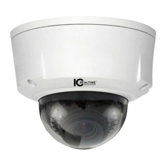
- Page 1 HD (IR) Vandal Proof Network Dome Camera User’s Manual Version 1.4.0...
- Page 2 Welcome Thank you for purchasing our network camera! This user’s manual is designed to be a reference tool for your system. Please read the following safeguard and warnings carefully before you use this series product! Please keep this user’s manual well for future reference!
- Page 3 Important Safeguards and Warnings 1.Electrical safety All installation and operation here should conform to your local electrical safety codes. The power shall conform to the requirement in the SELV (Safety Extra Low Voltage) and the Limited power source is rated 12V DC or 24V AC in the IEC60950-1. (Refer to general introduction) Please note: Do not connect two power supplying sources to the device at the same time;...
- Page 4 Do not touch the CCD (CMOS) optic component. You can use the blower to clean the dust on the lens surface. Always use the dry soft cloth to clean the device. If there is too much dust, please use the water to dilute the mild detergent first and then use it to clean the device.
-
Page 5: Table Of Contents
Table of Contents General Introduction ......................1 Overview ........................1 Features ........................1 Specifications ......................2 1.3.1 Performance ...................... 2 Structure ..........................4 Dimensions ....................... 4 Port Description ......................4 Bidirectional talk ....................... 8 2.3.1 Device-end to PC-end ..................9 2.3.2 PC-end to the Device-end ................ - Page 6 Overview ......................... 20 Operation ........................ 20 Web Operation ........................22 Network Connection....................22 Login and Main Interface ..................22 FAQ ............................24 Appendix Toxic or Hazardous Materials or Elements ............. 25...
-
Page 7: General Introduction
1 General Introduction 1.1 Overview This series network camera integrates the traditional camera and network video technology. It adopts audio and video data collection, transmission together. It can connect to the network directly without any auxiliary device. This series network camera uses standard H.264 and MJPEG video compression technology and G.711a audio compression technology, which maximally guarantee the audio and video quality. -
Page 8: Specifications
time; it may result in device damage! Log function Support PAL/NTSC Day/Night mode auto switch (electromagnetic ICR switch). Support iris auto adjust. Assistant Built-in IR light. Support IR night vision. Function Backlight compensation: screen auto split to realize backlight compensation to adjust the bright. - Page 9 Privacy Mask Supports max 4 privacy mask zones Video Setup Support parameter setup such as bright, contrast. Video Channel title, time title, motion detect, privacy mask. Information Lens 3~9mm@F1.2 motorized zoom focus lens Lens Interface CS. Lens is the default accessories. Audio Input 1-channe, RCA audio input Audio Output...
-
Page 10: Structure
2 Structure 2.1 Dimensions You can refer to the following figures for dimension information. The Unit is mm. See Figure 2-1 and Figure 2-2. Figure 2-1 Dimension 1 Figure 2-2 Dimension 2 2.2 Port Description For the non-IR series product, the interface is shown as in Figure 2-3 and Figure 2-4. - Page 11 Figure 2-3 Port 1 Figure 2-4 Port 2 For the IR motorized zoom lens series product, the interface is shown as in Figure 2-5 and Figure 2-6.
- Page 12 Figure 2-5 Port 3 Figure 2-6 Port 4 For the IR manual zoom lens series product, the interface is shown as in Figure 2-7 and Figure 2-8.
- Page 13 Figure 2-7 Port 5 Figure 2-8 Port 6 Please refer to the following sheet for external connection port definition information. Port Port Name Connector Function Description AC 24V power POWER Connect to AC 24V power. port DC 12V power POWER Connect to DC 12V power.
-
Page 14: Bidirectional Talk
external connected cable RJ45 network Ethernet port Network cable port. port It includes alarm input/output, audio I/O port and analog output. Reset button. It is to restore factory RESET Reset button default setup. Adjust lens angle of view and AUTO definition. -
Page 15: Device-End To Pc-End
2.3.1 Device-end to PC-end Device Connection Please connect the speaker or the MIC to the audio input port of the device. Then connect the earphone to the audio output port of the PC. Login the Web and then click the Talk button to enable the bidirectional talk function. You can see the button becomes orange after you enabled the bidirectional talk function. - Page 16 Figure 2-9 Alarm Please refer to the following figure for alarm input information. See Figure 2-10. Alarm input: When the input signal is idle or grounded, the device can collect the different statuses of the alarm input port. When the input signal is connected to the 5V or is idle, the device collects the logic “1”. When the input signal is grounded, the device collects the logic “0”.
- Page 17 Figure 2-11 Alarm output...
-
Page 18: Installation
3 Installation Important Before you complete the installation and setup, do not remove the electrostatic attraction film on the transparent enclosure. Otherwise it may result in injury. After remove electrostatic attraction film, do not touch dome enclosure in case it may leave stain. - Page 19 IR Motorized Zoom Lens Series Non-IR Series IR Manual Zoom Series Figure 3-2 General installation Step 1 Take the installation position map from the accessories bag and then paste it on the installation ceiling or the wall according to the monitor area. Please dig three bottom holes of the plastic expansion bolts according to the map.
- Page 20 Figure 3-3 Installation 2 Step 4 Adjust the chassis of the device to the proper position and pull the cable to the cable exit of the installation surface. Line up the holes of the chassis to the three expansion bolt holes you dug in Step 1. Take three ST3.0 self-tapping screws and secure them in the three plastic expansion bolts.
- Page 21 Adjust the lens to the proper angle according to your monitor requirements. a) For the IR series product, you can skip current step and go the step b) directly. For the non-IR series product, push the port slightly to remove the decoration enclosure from the black plastic enclosure. See Figure 3-5.
-
Page 22: Manual Zoom Lens Focus Operation
d). Image pan rotation angle setup. Please refer to Figure 3-7 to turn lock screw D to adjust the video pan angle. Then fix the lock screw B and C. The video pan angle ranges from 0° ~+350° . Lock screw B/C Adjust lens tilt rotation angle. -
Page 23: Side Cable Exit
Slightly loosen the adjusting screw F and push the adjust screw F to make it swing. Adjust the lens to get the clear video and then fix the adjusting screw firmly. Step 3 When you are securing the adjusting screw F, you can see the video may become blur. Please push the adjusting screw E to adjust the video slightly. -
Page 24: Micro Sd Card Installation
The device reserves two cable exits. The pin diameter shall be less than 15mm. One of the cable exits has M22 screw thread and can work with the default combination cable to remove the risk of the dragging and pulling of the cable. The device has two waterproof airproof plugs (One default position is the cable exit of the chassis of the device and the other is in the accessories bag.). - Page 25 Step 2 Please find the “Micro SD” mark inside the device and adjust the Micro SD card direction according to prompt direction. Insert the card to the slot and then install the Micro SD card. See Figure 3-11. Figure 3-11 Micro SD card Step 3 Please refer to Step 7 in chapter 3.2.1 to put the device protection enclosure back.
-
Page 26: Quick Configuration Tool
4 Quick Configuration Tool 4.1 Overview Quick configuration tool can search current IP address, modify IP address. At the same time, you can use it to upgrade the device. Please note the tool only applies to the IP addresses in the same segment. 4.2 Operation Double click the “ConfigTools.exe”... - Page 27 In the configuration tool search interface (Figure 4-1), please select a device IP address and then double click it to open the login interface. Or you can select an IP address and then click the Login button to go to the login interface. See Figure 4-3. In Figure 4-3, you can view device IP address, user name, password and port.
-
Page 28: Web Operation
5 Web Operation This series network camera products support the Web access and management via PC. Web includes several modules: Monitor channel preview, system configuration, alarm and etc. 5.1 Network Connection Please follow the steps listed below for network connection. ... - Page 29 Figure 5- 2 Web login After you successfully logged in, please install WEB plug-in unit. Please refer to the Web Operation Manual included in the resource CD for detailed operation instruction. See Figure 5- 3. Figure 5- 3 Web monitoring window...
-
Page 30: Faq
6 FAQ I can not boot up Please click RESET button for at least five seconds to restore the device. factory default setup. Micro card Do not set the Micro SD card as the storage media to storage the write times schedule record file. -
Page 31: Appendix Toxic Or Hazardous Materials Or Elements
Appendix Toxic or Hazardous Materials or Elements Toxic or Hazardous Materials or Elements Component Name Cr VI PBDE Circuit Board ○ ○ ○ ○ ○ ○ Component ○ ○ ○ ○ ○ ○ Device Case ○ ○ ○ ○ ○ ○...
Need help?
Do you have a question about the ICIP-D2000VIR-B and is the answer not in the manual?
Questions and answers