Table of Contents
Advertisement
Quick Links
Tel +1 (717) 767-6511
Fax +1 (717) 764-0839
www.redlion.net
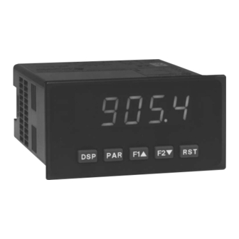
MODEL DP5 – 1/8 DIN ANALOG INPUT PANEL METERS
U
L
C
US LISTED
US LISTED
4
IND. CONT . EQ.
GENERAL DESCRIPTION
The DP5 Panel Meters offer many features and performance capabilities to
suit a wide range of industrial applications. These meters are available in three
different models to handle various analog inputs, including DC Voltage/Current,
Process, and Temperature Inputs. Refer to pages 4 and 5 for the details on the
specific models.
The meters provide a MAX and MIN reading memory with programmable
capture time. The capture time is used to prevent detection of false max or min
readings which may occur during start-up or unusual process events.
The signal totalizer (integrator) can be used to compute a time-input product.
This can be used to provide a readout of totalized flow, calculate service
intervals of motors or pumps, etc. The totalizer can also accumulate batch
weighing operations.
Once the meters have been initially configured, the parameter list may be
locked out from further modification.
The meters have been specifically designed for harsh industrial environments.
With NEMA 4X/IP65 sealed bezel and extensive testing of noise effects to CE
requirements, the meter provides a tough yet reliable application solution.
DIMENSIONS In inches (mm)
Courtesy of Steven Engineering, Inc. ● 230 Ryan Way, South San Francisco, CA 94080-6370 ● General Inquiries: (800) 670-4183 ● www.stevenengineering.com
51EB
Note: Recommended minimum clearance (behind the panel) for mounting clip installation is
PROCESS, VOLTAGE, CURRENT, AND TEMPERATURE INPUTS
5-DIGIT 0.56" HIGH LED DISPLAY
PROGRAMMABLE FUNCTION KEYS/USER INPUT
9 DIGIT TOTALIZER (INTEGRATOR) WITH BATCHING
OPTIONAL CUSTOM UNITS OVERLAY W/BACKLIGHT
NEMA 4X/IP65 SEALED FRONT BEZEL
SAFETY SUMMARY
All safety related regulations, local codes and instructions that appear in this
literature or on equipment must be observed to ensure personal safety and to
prevent damage to either the instrument or equipment connected to it. If
equipment is used in a manner not specified by the manufacturer, the protection
provided by the equipment may be impaired.
CAUTION: Risk of Danger.
Read complete instructions prior to
installation and operation of the unit.
2.1" (53.4) H x 5.0" (127) W.
1
Bulletin No. DP5-E
Drawing No. LP0546
Released 12/07
CAUTION: Risk of electric shock.
Advertisement
Chapters
Table of Contents

Subscribe to Our Youtube Channel
Related Manuals for red lion DP5


Summary of Contents for red lion DP5
- Page 1 GENERAL DESCRIPTION SAFETY SUMMARY The DP5 Panel Meters offer many features and performance capabilities to All safety related regulations, local codes and instructions that appear in this suit a wide range of industrial applications. These meters are available in three...
-
Page 2: Table Of Contents
ABLE ONTENTS Ordering Information ....2 Setting the Jumpers ....6 General Meter Specifications. -
Page 3: General Meter Specifications
ENERAL ETER PECIFICATIONS 1. DISPLAY: 5 digit, 0.56" (14.2 mm) red LED, (-19999 to 99999) 14. ENVIRONMENTAL CONDITIONS: 2. POWER: Operating Temperature Range: 0 to 50°C AC Versions: Storage Temperature Range: -40 to 60°C AC Power: 85 to 250 VAC, 50/60 Hz, 10 VA Operating and Storage Humidity: 0 to 85% max. - Page 4 DP5D - U DC I ODEL NIVERSAL NPUT FOUR VOLTAGE RANGES (300 VDC Max) FIVE CURRENT RANGES (2A DC Max) 24 VDC TRANSMITTER POWER DP5D SPECIFICATIONS INPUT RANGES: INPUT ACCURACY* ACCURACY* IMPEDANCE/ CONTINUOUS RESOLUTION RANGE (18 to 28°C) (0 to 50°C) COMPLIANCE OVERLOAD 0.03% of reading...
-
Page 5: Accessories
DP5T - T RTD I ODEL HERMOCOUPLE AND NPUT THERMOCOUPLE AND RTD INPUTS CONFORMS TO ITS-90 STANDARDS TIME-TEMPERATURE INTEGRATOR DP5T SPECIFICATIONS READOUT: Resolution: Variable: 0.1, 0.2, 0.5, or 1, 2, or 5 degree Scale: F or C Offset Range: -19,999 to 99,999 display units RTD INPUTS: THERMOCOUPLE INPUTS: Type: 3 or 4 wire, 2 wire can be compensated for lead wire resistance... - Page 6 The panel The DP5 meets NEMA 4X/IP65 requirements for indoor use when properly latch should be engaged in the farthest forward slot possible. To achieve a installed.
- Page 7 DP5P Jumper Selection Main JUMPER SELECTIONS Circuit indicates factory setting. Board USER INPUT JUMPER LOCATION DP5T Jumper Selection RTD Input Jumper One jumper is used for RTD input ranges. Select the proper range to match the RTD probe being used. It is not necessary to remove this jumper when not using RTD probes. Main Circuit JUMPER SELECTIONS...
- Page 8 3.1 POWER WIRING AC Power DC Power Terminal 1: VAC Terminal 1: +VDC Terminal 2: VAC Terminal 2: -VDC 3.2 INPUT SIGNAL WIRING DP5D INPUT SIGNAL WIRING Before connecting signal wires, the Input Range Jumper should be verified for proper position. Voltage Signal Current Signal Current Signal (2 wire...
- Page 9 DP5T INPUT SIGNAL WIRING CAUTION: Sensor input common is NOT isolated Thermocouple 3-Wire RTD 2-Wire RTD from user input common. In order to preserve the safety of the meter application, the sensor input common must be suitably isolated from hazardous live earth referenced voltages;...
- Page 10 5.0 P ROGRAMMING THE ETER OVERVIEW PROGRAMMING MENU STEP BY STEP PROGRAMMING INSTRUCTIONS: DISPLAY MODE The meter normally operates in the Display Mode. In this mode, the meter displays can be viewed consecutively by pressing the key. The PROGRAMMING MODE ENTRY (PAR KEY) annunciators to the left of the display indicate which display is currently shown;...
- Page 11 5.1 MODULE 1 - S IGNAL NPUT ARAMETERS PARAMETER MENU DP5T PARAMETER MENU Refer to the appropriate Input Range for the selected TEMPERATURE SCALE meter. Use only one Input Range, then proceed to Display Decimal Point. °F °C Select the temperature scale. This selection applies for Input, MAX, MIN, DP5D INPUT RANGE and TOT displays.
- Page 12 FILTER SETTING* INPUT VALUE FOR SCALING POINT 2 seconds The input filter setting is a time constant expressed in tenths of a second. The For Key-in ( ), enter the known second Input Value by using the arrow filter settles to 99% of the final display value within approximately 3 time keys.
- Page 13 5.2 MODULE 2 - U NPUT AND RONT ANEL UNCTION ARAMETERS PARAMETER MENU The user input is programmable to perform specific meter control functions. RELATIVE/ABSOLUTE DISPLAY While in the Display Mode or Program Mode, the function is executed the instant the user input transitions to the active state. The front panel function keys are also individually programmable to perform specific meter control functions.
- Page 14 RESET TOTALIZER RESET, SELECT, ENABLE MAXIMUM DISPLAY When activated (momentary action), the Maximum value is set to the present Input Display value. Maximum continues from that value while active (maintained action). When the user input is released, Maximum detection stops and holds its When activated (momentary action), flashes and the Totalizer resets to value.
- Page 15 5.4 MODULE 4 - S ECONDARY UNCTION ARAMETERS PARAMETER MENU MAX CAPTURE DELAY TIME* DISPLAY OFFSET VALUE* sec. This parameter does not apply for the DP5T. When the Input Display is above the present MAX value for the entered delay time, the meter will capture that display value as the new MAX reading. A delay time helps to avoid false captures of sudden short spikes.
- Page 16 5.5 MODULE 5 - T OTALIZER NTEGRATOR ARAMETERS PARAMETER MENU TOTALIZER HIGH ORDER DISPLAY The totalizer accumulates (integrates) the Input Display value using one of When the total exceeds 5 digits, the front panel annunciator TOT flashes. In two modes. The first is using a time base. This can be used to compute a time- this case, the meter continues to totalize up to a 9 digit value.
- Page 17 5.9 MODULE 9 - F ACTORY ERVICE PERATIONS PARAMETER MENU RESTORE FACTORY DEFAULTS DP5P - Input Calibration Use the arrow keys to display and press PAR. WARNING: Calibration of this meter requires a signal source with an The meter will display and then return to accuracy of 0.01% or better.
- Page 18 The Company disclaims all liability for any affirmation, promise or representation with respect to the products. The customer agrees to hold Red Lion Controls harmless from, defend, and indemnify RLC against damages, claims, and expenses arising out of subsequent sales of RLC products or products...
- Page 19 PARAMETER VALUE CHART Programmer ________________ Date ________ DP5 Model Number _______ Meter# _____________ Security Code __________ Secondary Function Parameters 4-SEC 1-INP Signal Input Parameters FACTORY FACTORY DISPLAY PARAMETER USER SETTING DISPLAY PARAMETER USER SETTING SETTING SETTING 0. 1 HI-t MAX CAPTURE DELAY TIME...
- Page 20 DP5 PROGRAMMING QUICK OVERVIEW Courtesy of Steven Engineering, Inc. ● 230 Ryan Way, South San Francisco, CA 94080-6370 ● General Inquiries: (800) 670-4183 ● www.stevenengineering.com...
- Page 21 With an RS232 or RS485 The PAX Digital Input Panel Meters offer many features and performance card installed, it is possible to configure the meter using Red Lion’s Crimson capabilities to suit a wide range of industrial applications. Available in three software.
- Page 22 ABLE ONTENTS Ordering Information ....2 Installing Plug-In Cards ....8 General Meter Specifications.
- Page 23 ENERAL ETER PECIFICATIONS DISPLAY: 6 digit, 0.56" (14.2 mm) red sunlight readable or standard green ELECTROMAGNETIC COMPATIBILITY Immunity to EN 50082-2 2. POWER: Electrostatic discharge EN 61000-4-2 Level 2; 4 Kv contact AC Versions: Level 3; 8 Kv air AC Power: 85 to 250 VAC, 50/60 Hz, 18 VA Electromagnetic RF fields EN 61000-4-3 Level 3;...
- Page 24 PAXC - 1/8 DIN C ODEL OUNTER 6-DIGIT LED DISPLAY (Alternating 8 digits for counting) DUAL COUNT QUAD INPUTS UP TO 3 COUNT DISPLAYS SETPOINT ALARM OUTPUTS (W/Plug-in card) PAXC SPECIFICATIONS ANNUNCIATORS: MAXIMUM SIGNAL FREQUENCIES: A - Counter A To determine the maximum frequency for the input(s), first answer the B - Counter B questions with a yes (Y) or no (N).
- Page 25 PAXI - 1/8 DIN C ODEL OUNTER ETER COUNT, RATE AND SLAVE DISPLAY 6-DIGIT 0.56" RED SUNLIGHT READABLE DISPLAY VARIABLE INTENSITY DISPLAY 10 POINT SCALING (FOR NON-LINEAR PROCESSES) FOUR SETPOINT ALARM OUTPUTS (W/OPTION CARD) RETRANSMITTED ANALOG OUTPUT (W/OPTION CARD) COMMUNICATION AND BUS CAPABILITIES (W/OPTION CARD) BUS CAPABILITIES;...
- Page 26 PTIONAL UTPUT ARDS SETPOINT CARDS (PAXCDS) WARNING: Disconnect all power to the unit before installing Plug-in cards. The PAX and MPAX series has 4 available setpoint alarm output plug-in cards. Only one of these cards can be installed at a time. (Logic state of the outputs can be reversed in the programming.) These plug-in cards include: Adding Option Cards PAXCDS10 - Dual Relay, FORM-C, Normally open &...
- Page 27 1.0 I NSTALLING THE ETER Installation While holding the unit in place, push the panel latch over the rear of the unit so that the tabs of the panel latch engage in the slots on the case. The panel The PAX meets NEMA 4X/IP65 requirements when properly installed. The latch should be engaged in the farthest forward slot possible.
- Page 28 3.0 I NSTALLING ARDS The Plug-in cards are separately purchased optional cards that perform To Install: specific functions. These cards plug into the main circuit board of the meter. The 1. With the case open, locate the Plug-in card connector for the card type to be Plug-in cards have many unique functions when used with the PAX.
- Page 29 4.0 W IRING THE ETER WIRING OVERVIEW b. Connect the shield to earth ground at both ends of the cable, usually when the noise source frequency is above 1 MHz. Electrical connections are made via screw-clamp terminals located on the c.
- Page 30 4.3 INPUT WIRING CAUTION: Sensor input common is NOT isolated from user input common. In order to preserve the safety of the meter application, the sensor input common must be suitably isolated from hazardous live earth referenced voltage; or input common must be at protective earth ground potential. If not, hazardous voltage may be present at the User Inputs and User Input Common terminals.
- Page 31 4.5 PAXI SERIAL COMMUNICATION WIRING RS232 Communications RS485 Communications The RS485 communication standard allows the connection of up to 32 devices on a single pair of wires, distances up to 4,000 ft. and data rates as high as 10M baud (the PAX is limited to 19.2k baud). The same pair of wires is used to both transmit and receive data.
- Page 32 6.0 P ROGRAMMING THE ETER OVERVIEW PROGRAMMING MENU Shaded areas represent program access that is model dependent. PROGRAMMING MODE ENTRY (PAR KEY) PROGRAMMING MODE EXIT (DSP KEY or at PAR KEY) The meter normally operates in the Display Mode. No parameters can be The Programming Mode is exited by pressing the key (from anywhere programmed in this mode.
- Page 33 COUNTER A OPERATING MODE COUNTER A SCALE MULTIPLIER * NONE cntud dcntud quAd1 quAd2 quAd4 dquAd1 dquAd2 cnt2 cntud2 dctud2 The number of input counts is multiplied by the scale multiplier and the scale Select the operating mode for Counter A. factor to obtain the desired process value.
- Page 34 COUNTER B OPERATING MODE COUNTER B RESET POWER-UP * NONE dcntud dquAd1 dquAd2 cnt2 dctud2 Counter B may be programmed to reset at each meter power-up. Select the operating mode for Counter B. SELECTION MODE DESCRIPTION Factory Setting can be used without affecting basic start-up. Does not count.
- Page 35 6.2 MODULE 2 - U NPUT AND RONT ANEL UNCTION ARAMETERS PARAMETER MENU Module 2 is the programming for rear terminal user inputs and front panel EXCHANGE PARAMETER LISTS function keys. Three rear terminal user inputs are individually programmable to perform specific meter control functions.
- Page 36 MAINTAINED (LEVEL) RESET AND INHIBIT DEACTIVATE SETPOINT MAINTAINED (LEVEL) The meter deactivates the setpoints configured as , as long as activated The meter performs a reset and inhibits the displays configured as , as (maintained action). This action only functions with a Setpoint card installed. long as activated (maintained action).
- Page 37 6.3 MODULE 3 - D ISPLAY AND ROGRAM ARAMETERS PARAMETER MENU x = Counter A , Counter B, and then Counter C Shaded areas represent program access that is model dependent. n = Setpoints 1 to 4 Module 3 is the programming for Display lock-out and “Full” and “Quick” SETPOINT 1 to 4 ACCESS LOCK-OUT * Program lock-out.
- Page 38 6.4 MODULE 4 - R PAXR & I NPUT ARAMETERS PARAMETER MENU Non-linear Application – Up to 10 Scaling Points Module 4 is the programming for the Rate parameters. For maximum input frequency, Rate assignment should be set to when not in use. When set to Non-linear processes may utilize up to nine segments (ten scaling points) to , the remaining related parameters are not accessible.
- Page 39 RATE INPUT VALUE FOR SCALING POINT 2 RATE SCALING To scale the Rate, enter a Scaling Display value with a corresponding Scaling Input value. (The Display and Input values can be entered by Key-in or Applied Methods.) These values are internally plotted to a Display value of 0 and Input value of 0 Hz.
- Page 40 6.5 MODULE 5 - C OUNTER NPUT ARAMETERS PAXC & I PARAMETER MENU Module 5 is the programming for Counter C. For maximum input frequency, the counter operating mode should be set to when not in use. When set to COUNTER C SCALE FACTOR the remaining related parameters are not accessible.
- Page 41 6.6 MODULE 6 - S ETPOINT LARM ARAMETERS PARAMETER MENU Module 6 is the programming for the setpoint (alarms) output parameters. To have setpoint outputs, a setpoint Plug-in card needs to be installed into the PAX (see Ordering Information). Depending on the card installed, there will be two or four setpoint outputs available.
- Page 42 SETPOINT ACTION SETPOINT STANDBY OPERATION * Selecting will disable low acting setpoints at a power up until the display : When not using a setpoint, it should be set to (no action). value crosses into the alarm “off” area. Once in the alarm “off” area, the For Counter Assignments: setpoint will function according to the configured setpoint parameters.
- Page 43 PAXC & I: SETPOINT RESET WITH DISPLAY RESET * PAXC & I: SETPOINT RESET WHEN SPn+1 DEACTIVATES * Select , so the setpoint output will deactivate (reset) when the Setpoint Select , so the setpoint output will deactivate (reset) when SPn +1 Assignment ( ) counter display resets.
- Page 44 2 digit address number must be assigned to each meter. ASCII characters. Red Lion's SFPAX software can be used for configuring the PAXI (See Ordering Information). For serial hardware and wiring details, refer to section 4.5 Serial Communication Wiring.
- Page 45 SENDING SERIAL COMMANDS AND DATA Command String Examples: 1. Address = 17, Write 350 to Setpoint 1 When sending commands to the meter, a string containing at least one String: N17VM350$ command character must be constructed. A command string consists of a command character, a value identifier, numerical data (if writing data to the 2.
- Page 46 Auto/Manual Mode Register (MMR) ID: U Writing to this register (VW) while the analog output is in the Manual Mode causes the output signal level to update immediately to the value sent. While in This register sets the controlling mode for the outputs. In Auto Mode (0) the the Automatic Mode, this register may be written to, but it has no effect until the meter controls the setpoint and analog output.
- Page 47 COMMAND RESPONSE TIME SERIAL TIMING The meter can only receive data or transmit data at any one time (half-duplex PROCESS TIME (t COMMAND COMMENT operation). During RS232 transmissions, the meter ignores commands while Numeric Slave 2-50 msec. transmitting data, but instead uses RXD as a busy signal. When sending Reset 2-50 msec.
- Page 48 6.8 MODULE 8 - A NALOG UTPUT ARAMETERS PAXI O PARAMETER MENU Module 8 is the programming for the analog output parameters. To have an ANALOG LOW SCALE VALUE analog output signal, an analog output plug-in card needs to be installed (See Ordering Information).
- Page 49 Analog Output Card Calibration PAXI: CALIBRATION Before starting, verify that a precision meter with an accuracy of 0.05% or The only item in the PAXI meter that can be calibrated better (voltmeter for voltage output and/or current meter for current output) is is the Analog Output.
- Page 50 PARAMETER VALUE CHART Programmer ________________ Date ________ PAX Model Number _________ Meter# _____________ Security Code __________ Counter A & B Input Parameters - PAXC & I only 4-rtE Rate Input Parameters - PAXI & R only 1-INP FACTORY FACTORY DISPLAY PARAMETER USER SETTING DISPLAY...
- Page 51 The Company disclaims all liability for any affirmation, promise or representation with respect to the products. The customer agrees to hold Red Lion Controls harmless from, defend, and indemnify RLC against damages, claims, and expenses arising out of subsequent sales of RLC products or products...
- Page 52 PROGRAMMING QUICK OVERVIEW Courtesy of Steven Engineering, Inc. ● 230 Ryan Way, South San Francisco, CA 94080-6370 ● General Inquiries: (800) 670-4183 ● www.stevenengineering.com...
- Page 53 Bulletin No. PAXCK-G Drawing No. LP0524 Released 2/08 Tel +1 (717) 767-6511 Fax +1 (717) 764-0839 www.redlion.net MODEL PAX-1/8 DIN PRESET TIMER (PAXTM) & REAL-TIME CLOCK (PAXCK) 6-DIGIT 0.56" RED SUNLIGHT READABLE DISPLAY 4 SEPARATE DISPLAYS (Timer, Counter, Real-Time Clock, and Date) CYCLE COUNTING CAPABILITY PROGRAMMABLE FUNCTION KEYS/USER INPUTS FOUR SETPOINT ALARM OUTPUTS (W/Plug-in card)
-
Page 54: Installing The Meter
ABLE ONTENTS Ordering Information ....2 Wiring the Meter ..... . 6 General Meter Specifications. - Page 55 ENERAL ETER PECIFICATIONS DISPLAY: 6 digit, 0.56" (14.2 mm) red sunlight readable or standard green 12. MEMORY: Non-volatile E PROM retains all programming parameters and display values. 2. POWER: 13. ENVIRONMENTAL CONDITIONS: AC Versions (PAXCK000, PAXTM000): Operating Temperature Range: 0 to 50°C (0 to 45°C with all three plug-in AC Power: 85 to 250 VAC, 50/60 Hz, 18 VA cards installed) Isolation: 2300 Vrms for 1 min.
- Page 56 PTIONAL ARDS AND CCESSORIES SETPOINT CARDS (PAXCDS) WARNING: Disconnect all power to the unit before installing Plug-in cards. The PAX and MPAX series has 4 available setpoint alarm output plug-in cards. Only one of these cards can be installed at a time. (Logic state of the outputs can be reversed in the programming.) These plug-in cards include: Adding Option Cards The PAX and MPAX series meters can be fitted with up to three optional plug-...
-
Page 57: Setting The Jumpers
1.0 I NSTALLING THE ETER Installation The meter meets NEMA 4X/IP65 requirements for indoor use when properly While holding the meter in place, push the panel latch over the rear of the installed. The meter is intended to be mounted into an enclosed panel. Prepare meter so that the tabs of the panel latch engage in the slots on the case. -
Page 58: Wiring The Meter
3.0 I NSTALLING ARDS The Plug-in cards are separately purchased optional cards that perform To Install: specific functions. These cards plug into the main circuit board of the meter. The 1. With the case open, locate the Plug-in card connector for the card type to be Plug-in cards have many unique functions when used with the meters. - Page 59 4.1 POWER WIRING AC Power DC Power Terminal 1: VAC Terminal 1: +VDC Terminal 2: VAC Terminal 2: -VDC 4.2 TIMER INPUT WIRING Before connecting the wires, the Timer Input logic jumper should be verified for proper position. Two Wire Proximity, Current Source Current Sinking Output Current Sourcing Output Switch or Isolated Transistor;...
- Page 60 4.4 SETPOINT (ALARMS) WIRING SOURCING OUTPUT LOGIC CARD SETPOINT PLUG-IN CARD TERMINALS SINKING OUTPUT LOGIC CARD 4.5 SERIAL COMMUNICATION WIRING RS232 Communications RS485 Communications The RS485 communication standard allows the connection of up to 32 devices on a single pair of wires, distances up to 4,000 ft. and data rates as high as 10M baud (the PAX is limited to 19.2k baud).
-
Page 61: Reviewing The Front Buttons And Display
4.6 REAL-TIME CLOCK WIRING (PAXCK) Time synchronization between multiple PAXCK meters can be accomplished through a hardware interface on the Real-Time Clock option card. This RS485 type interface allows connection of up to 32 PAXCK meters in a two-wire multidrop network, at distances up to 4000 ft. In a synchronization network, one PAXCK meter is programmed as the Host, while all other meters are programmed as Slaves. - Page 62 6.0 P ROGRAMMING THE ETER OVERVIEW PROGRAMMING MENU DISPLAY MODE module in sequence. Note that Modules 5 through 8 are only accessible when The meter normally operates in the Display Mode. In this mode, the meter the appropriate plug-in option card is installed. If lost or confused while displays can be viewed consecutively by pressing the key.
- Page 63 6.1 MODULE 1 - T IMER NPUT ARAMETERS PARAMETER MENU Module 1 is the programming module for the Timer Input Parameters. In the Display Mode, the TMR annunciator indicates the Timer display is currently being shown. An EXCHANGE PARAMETER LISTS feature, which includes Edge Triggered Operation - 2 Input Edge Triggered Operation - 2 Input, with Display Hold...
- Page 64 FLASH TIMER ANNUNCIATOR TIMER RESET AT POWER-UP This parameter allows the Timer annunciator (TMR) to flash when the Timer The Timer can be programmed to Reset at each meter power-up. is running or stopped/inhibited. Select if a flashing indicator is not desired. TIMER INPUT STATE AT POWER-UP Determines the “Run/Stop”...
- Page 65 DISPLAY SELECT (Level Active) DISPLAY HOLD (Level Active) When active (maintained action), the meter continuously scrolls through all When active (maintained action), the meter “freezes” the display values displays that are not “locked-out” in the Display mode. (See Module 3 for entered as in the sublist, while normal meter operation continues internally.
- Page 66 CHANGE DISPLAY INTENSITY LEVEL OUTPUT SET (Level Active) When activated (maintained action), the meter continually activates the When activated (momentary action), the display intensity changes to the next intensity level (of 4). The four levels correspond to Display Intensity Level output for all Setpoints entered as in the sublist.
- Page 67 6.3 MODULE 3 - D ISPLAY AND ROGRAM ARAMETERS PARAMETER MENU ** These parameters only appear if a Setpoint option card is installed. = Setpoint Number 1 thru 4 Module 3 is the programming module for setting the Display Lock-out TIMER &...
- Page 68 6.4 MODULE 4 - C YCLE OUNTER ARAMETERS PARAMETER MENU Module 4 is the programming module for the Cycle Counter Parameters. In the CYCLE COUNTER START VALUE Display Mode, the CNT annunciator indicates the Cycle Counter display is currently being shown. An EXCHANGE PARAMETER LISTS feature, which includes the Cycle Counter Start and Stop Values, is explained in Module 2.
- Page 69 Timing Diagrams for Predefined Timer Operating Modes NOTE: Input A is shown as a Sourcing input (active high). If a Sinking input (active low) is used, the logic levels for Input A would be inverted. On-Delay / Interval Timing On-Delay Timing Input A Input A Output 1...
- Page 70 6.6 MODULE 6 - S ETPOINT LARM ARAMETERS This module can only be accessed if a Setpoint Card is installed. PARAMETER MENU = Setpoint Number 1 thru 4 Module 6 is the programming module for the Setpoint (Alarm) Output OUTPUT LOGIC Parameters.
- Page 71 TIME-OUT VALUE TIMER STOP The Time-Out Value only appears when the Setpoint Action ( ) is Timer stops when the Setpoint output activates ( ) or deactivates ( programmed for Timed Output mode ( ). In this mode, the Time-Out Value Select if the output should not affect the Timer Run/Stop status.
- Page 72 RTC values as numeric data only. This selection allows the RTC values to be recognized by the Red Lion HMI products. RTC Time/Date units are separated by a “.”. The Day is sent as a DATA BITS single number as shown below.
- Page 73 SERIAL RTC MASTER ADDRESSING Register Identification Chart A meter, having software code version 2.3 or greater, with a Real Time Clock REGISTER VALUE DESCRIPTION COMMAND TRANSMIT DETAILS NAME Card and an RS485 Serial Communication Card installed, can act as a Serial RTC Master, when programmed with meter address 98 or 99.
- Page 74 SP1 printout = 12:00 P. character besides 0 or 1 in a field or if the corresponding output was not first in Note: When communicating with a Red Lion Controls HMI unit, set manual mode, the corresponding output value will not change.
- Page 75 COMMUNICATION FORMAT Data is transferred from the meter through a serial communication channel. Start Bit and Data Bits In serial communications, the voltage is switched between a high and low level Data transmission always begins with the start bit. The start bit signals the at a predetermined rate (baud rate) using ASCII encoding.
- Page 76 TIME DISPLAY FORMAT To calibrate the RTC, install the meter in its normal operating environment, and set the time based on a known accurate reference (such as the WWV broadcast or the Atomic Clock reference which is available via the 12-59p 12-59 23-59...
- Page 77 The Company disclaims all liability for any affirmation, promise or representation with respect to the products. The customer agrees to hold Red Lion Controls harmless from, defend, and indemnify RLC against damages, claims, and expenses arising out of subsequent sales of RLC products or products...
-
Page 78: Parameter Value Chart
PARAMETER VALUE CHART Programmer ________________ Date ________ PAXCK Clock Timer Meter# _____________ Security Code __________ Display and Program Lock-out Parameters 3-LOC 1-INP Timer Input Parameters FACTORY FACTORY DISPLAY PARAMETER USER SETTING DISPLAY PARAMETER USER SETTING SETTING SETTING t-dSP TIMER DISPLAY LOCK-OUT rANGE SSSSSS TIMER RANGE... - Page 79 Setpoint (Alarm) Parameters 6-SPt SP-1 SP-2 SP-3 SP-4 FACTORY FACTORY FACTORY FACTORY DISPLAY PARAMETER USER SETTING USER SETTING USER SETTING USER SETTING SETTING SETTING SETTING SETTING ASM-n NONE NONE NONE NONE SETPOINT ASSIGNMENT ACt-n LAtCH LAtCH LAtCH LAtCH SETPOINT ACTION OUt-n OUTPUT LOGIC ON-n...
- Page 80 PAXTM/PAXCK PROGRAMMING QUICK OVERVIEW...
- Page 81 Bulletin No. PAX-H Drawing No. LP0545 Released 5/08 Tel +1 (717) 767-6511 Fax +1 (717) 764-0839 www.redlion.net MODEL PAX – 1/8 DIN ANALOG INPUT PANEL METERS PROCESS, VOLTAGE, CURRENT, TEMPERATURE, AND STRAIN GAGE INPUTS 5-DIGIT 0.56" RED SUNLIGHT READABLE DISPLAY VARIABLE INTENSITY DISPLAY 16 POINT SCALING FOR NON-LINEAR PROCESSES PROGRAMMABLE FUNCTION KEYS/USER INPUTS...
-
Page 82: Programming Overview
ABLE ONTENTS Ordering Information ....2 Installing the Meter ....8 General Meter Specifications . - Page 83 ENERAL ETER PECIFICATIONS DISPLAY: 5 digit, 0.56" (14.2 mm) red sunlight readable or standard green 13. CUSTOM LINEARIZATION: LEDs, (-19999 to 99999) Data Point Pairs: Selectable from 2 to 16 2. POWER: Display Range: -19,999 to 99,999 AC Versions: Decimal Point: 0 to 0.0000 AC Power: 85 to 250 VAC, 50/60 Hz, 15 VA PAXT: Ice Point Compensation: user value (0.00 to 650.00 µV/°C) Isolation: 2300 Vrms for 1 min.
- Page 84 PAXD - U DC I ODEL NIVERSAL NPUT FOUR VOLTAGE RANGES (300 VDC Max) FIVE CURRENT RANGES (2A DC Max) THREE RESISTANCE RANGES (10K Ohm Max) SELECTABLE 24 V, 2 V, 1.75 mA EXCITATION PAXD SPECIFICATIONS INPUT RANGES: INPUT ACCURACY* ACCURACY* IMPEDANCE/ CONTINUOUS...
- Page 85 PAXH - AC T RMS V ODEL OLT AND URRENT FOUR VOLTAGE RANGES (300 VAC Max) FIVE CURRENT RANGES (5 A Max) ACCEPTS AC OR DC COUPLED INPUTS THREE WAY ISOLATION: POWER, INPUT AND OUTPUTS PAXH SPECIFICATIONS INPUT RANGES: Isolation To Option Card Commons and User Input Commons: 125 Vrms Isolation To AC Power Terminals: 250 Vrms *Conditions for accuracy specification: INPUT...
- Page 86 PAXT - T RTD I ODEL HERMOCOUPLE AND NPUT THERMOCOUPLE AND RTD INPUTS CONFORMS TO ITS-90 STANDARDS CUSTOM SCALING FOR NON-STANDARD PROBES TIME-TEMPERATURE INTEGRATOR PAXT SPECIFICATIONS READOUT: Resolution: Variable: 0.1, 0.2, 0.5, or 1, 2, or 5 degrees Scale: F or C RTD INPUTS: Offset Range: -19,999 to 99,999 display units Type: 3 or 4 wire, 2 wire can be compensated for lead wire resistance...
-
Page 87: Installing Plug-In Cards
PTIONAL UTPUT ARDS SETPOINT CARDS (PAXCDS) WARNING: Disconnect all power to the unit before installing Plug-in cards. The PAX and MPAX series has 4 available setpoint alarm output plug-in cards. Only one of these cards can be installed at a time. (Logic state of the Adding Option Cards outputs can be reversed in the programming.) These plug-in cards include: The PAX and MPAX series meters can be fitted with up to three optional plug-... - Page 88 1.0 I NSTALLING THE ETER Installation While holding the unit in place, push the panel latch over the rear of the unit so that the tabs of the panel latch engage in the slots on the case. The panel The PAX meets NEMA 4X/IP65 requirements when properly installed. The latch should be engaged in the farthest forward slot possible.
- Page 89 PAXP Jumper Selection Main Circuit JUMPER SELECTIONS Board indicates factory setting. USER INPUT JUMPER LOCATION PAXH Jumper Selection CAUTION: To maintain the electrical safety of the meter, remove JUMPER SELECTIONS unneeded jumpers completely from the meter. Do not move the indicates factory setting.
-
Page 90: Wiring The Meter
PAXT Jumper Selection RTD Input Jumper One jumper is used for RTD input ranges. Select the proper range to match the RTD probe being used. It is not necessary to remove this jumper when Main not using RTD probes. Circuit Board JUMPER SELECTIONS indicates factory setting. - Page 91 3.2 INPUT SIGNAL WIRING PAXD INPUT SIGNAL WIRING Before connecting signal wires, the Input Range Jumper and Excitation Jumper should be verified for proper position. Voltage Signal Current Signal Current Signal (2 wire Current Signal (3 wire (self powered) (self powered) requiring excitation) requiring excitation) Terminal 4: -ADC...
- Page 92 PAXH INPUT SIGNAL WIRING Before connecting signal wires, the Signal, Input Range and Couple Jumpers should be verified for proper position. Voltage Signal Current Signal (Amps) Current Signal (Milliamps) CAUTION: Connect only one input signal range to the meter. Hazardous signal levels may be present on unused inputs.
- Page 93 3.3 USER INPUT WIRING Before connecting the wires, the User Input Logic Jumper should be verified for proper position. If not using User Inputs, then skip this section. Only the appropriate User Input terminal has to be wired. Sinking Logic Sourcing Logic Terminal 8-10: Terminal 8-10: + VDC thru external switching device...
- Page 94 5.0 P ROGRAMMING THE ETER OVERVIEW PROGRAMMING MENU STEP BY STEP PROGRAMMING INSTRUCTIONS: DISPLAY MODE The meter normally operates in the Display Mode. In this mode, the meter displays can be viewed consecutively by pressing the key. The PROGRAMMING MODE ENTRY (PAR KEY) annunciators to the left of the display indicate which display is currently shown;...
- Page 95 5.1 MODULE 1 - S IGNAL NPUT ARAMETERS PAX PARAMETER MENU PAXT PARAMETER MENU Refer to the appropriate Input Range for the selected PAXS INPUT RANGE meter. Use only one Input Range, then proceed to Display RANGE Decimal Point. SELECTION RESOLUTION 0.
- Page 96 DISPLAY ROUNDING* SCALING POINTS* These bottom selections are not Linear - Scaling Points (2) available for the PAXT. For linear processes, only 2 scaling points are necessary. It is recommended that the 2 scaling points be at opposite ends of the input signal being applied. Rounding selections other than one, cause the Input Display to ‘round’...
- Page 97 DISPLAY VALUE FOR SCALING POINT 2 4. The maximum scaled Display Value spread between range maximum and minimum is limited to 65,535. For example using +20 mA range the maximum +20 mA can be scaled to is 32,767 with 0 mA being 0 and Display Rounding of 1.
- Page 98 HOLD DISPLAY RESET MAXIMUM The shown display is held but all other meter functions When activated (momentary action), flashes and continue as long as activated (maintained action). the Maximum resets to the present Input Display value. The Maximum function then continues from that value. This selection functions independent of the selected display.
- Page 99 SETPOINT SELECTIONS PRINT REQUEST The following selections are accessible only with the Setpoint plug-in card installed. Refer to the Setpoint Card Bulletin shipped with the Setpoint plug-in card for an explanation of their operation. Select main or alternate setpoints The meter issues a block print through the serial port when activated.
- Page 100 5.4 MODULE 4 - S ECONDARY UNCTION ARAMETERS PARAMETER MENU UNITS LABEL BACKLIGHT* MAX CAPTURE DELAY TIME* sec. When the Input Display is above the present MAX value for the entered The Units Label Kit Accessory contains a sheet of custom unit overlays delay time, the meter will capture that display value as the new MAX reading.
- Page 101 5.5 MODULE 5 - T OTALIZER NTEGRATOR ARAMETERS PARAMETER MENU TOTALIZER HIGH ORDER DISPLAY The totalizer accumulates (integrates) the Input Display value using one of two modes. The first is using a time base. This can be used to compute a time- When the total exceeds 5 digits, the front panel annunciator TOT flashes.
- Page 102 Modules 6, 7, and 8 are accessible only with the appropriate plug-in cards installed. A quick overview of each Module is listed below. Refer to the corresponding plug-in card bulletin for a more detailed explanation of each parameter selection. 5.6 MODULE 6 - S ETPOINT LARM ARAMETERS...
- Page 103 5.9 MODULE 9 - F ACTORY ERVICE PERATIONS PARAMETER MENU DISPLAY INTENSITY LEVEL PAXP - Input Calibration Enter the desired Display Intensity Level (0-15) by WARNING: Calibration of this meter requires a signal source with an using the arrow keys. The display will actively dim or accuracy of 0.01% or better and an external meter with an accuracy brighten as the levels are changed.
- Page 104 100 OHM RTD Range Calibration AC Couple Offset Calibration - PAXH 1. Set the Input Range Jumper to 100 ohm. 2. Use the arrow keys to display and press PAR. Then choose It is recommended that Input Calibration be performed first. 1.
-
Page 105: Parameter Value Chart
TROUBLESHOOTING PROBLEM REMEDIES NO DISPLAY CHECK: Power level, power connections CHECK: Active (lock-out) user input PROGRAM LOCKED-OUT ENTER: Security code requested MAX, MIN, TOT LOCKED-OUT CHECK: Module 3 programming CHECK: Module 1 programming, Input Range Jumper position, input connections, input signal level, INCORRECT INPUT DISPLAY VALUE Module 4 Display Offset is zero, press DSP for Input Display PERFORM: Module 9 Calibration (If the above does not correct the problem.) - Page 106 User Input and Function Key Parameters Totalizer (Integrator) Parameters 2-FNC 5-tOt FACTORY FACTORY DISPLAY PARAMETER USER SETTING DISPLAY PARAMETER USER SETTING SETTING SETTING dECPt * TOTALIZER DECIMAL POINT USr-1 USER INPUT 1 tbASE TOTALIZER TIME BASE USr-2 USER INPUT 2 1.
- Page 107 PAX PROGRAMMING QUICK OVERVIEW...
- Page 108 The Company disclaims all liability for any affirmation, promise or representation with respect to the products. The customer agrees to hold Red Lion Controls harmless from, defend, and indemnify RLC against damages, claims, and expenses arising out of subsequent sales of RLC products or products...
- Page 109 GSD file REDL09D0.GSD. The GSD file and Address is set via rotary switches. The card’s address is read at power up. PAX bitmap can be downloaded from the Red Lion Controls website. SPECIFICATIONS 1. FIELDBUS TYPE: PROFIBUS-DP per standard EN 50170, implemented with Siemens SPC3 ASIC 2.
- Page 110 INSTALLING AN OPTION CARD TOP VIEW Caution: The option and main circuit cards contain static sensitive components. Before handling the cards, discharge static charges from your body by touching a grounded bare metal object. Ideally, handle the cards at a static controlled clean workstation.
- Page 111 PARAMETERIZATION DATA EXCHANGE The Polled Read Mask defines which PAX registers will be polled by the card Demand Write and Store Request Masks and therefore updated in the Input Data Block. The Polled Read Mask is a 32- The Demand Write Mask defines how data is written to the PAX. The bit integer with each bit mapped to a PAX register index.
- Page 112 bit 2: Setpoint 2 Output Status 1 = Output On bit 3: Setpoint 1 Output Status Red Lion Controls AP Red Lion Controls Red Lion Controls BV 31, Kaki Bukit Road 3, 20 Willow Springs Circle Basicweg 11b...
- Page 113 Bulletin No. PAXCDC2-D Drawing No. LP0424 Released 10/04 Tel +1 (717) 767-6511 Fax +1 (717) 764-0839 www.redlion.net MODEL PAXCDC -DEVICENET™ OUTPUT OPTION CARD DESCRIPTION The DeviceNet Option Card (PAXCDC30) is designed for the PAX series of Explicit Message Commands. The MAC ID and the Baud Rate are switch meters.
- Page 114 DeviceNet™ SPECIFICATIONS NETWORK STATUS LEDs Flashing Red LED: POWER SUPPLY This device is the only device on the network (waiting for an Source: Supplied by DeviceNet bus. acknowledgment to its duplicate MAC ID check), or an I/O connection The bus does not power the host. has timed out, or a recoverable error has occurred.
- Page 115 Attribute Identification Chart VALUE DESCRIPTION SERVICE CODES SUPPORTED POLLING STORE PAXI PAXCK PAXDP PAXI PAXCK PAXDP ➀ Data Swapping Flag G, S G, S G, S G, S Bit Strobe Attribute G, S G, S G, S G, S ➂ Polling Flags 1 G, S G, S...
- Page 116 The Company disclaims all liability for any affirmation, promise or representation with respect to the products. The customer agrees to hold Red Lion Controls harmless from, defend, and indemnify RLC against damages, claims, and expenses arising out of subsequent sales of RLC products or products...
- Page 117 Bulletin No. PAXCDC4-E Drawing No. LP0502 Released 8/07 Tel +1 (717) 767-6511 Fax +1 (717) 764-0839 www.redlion.net MODEL PAXCDC -MODBUS OUTPUT OPTION CARD DESCRIPTION This product bulletin covers the Communication Card for the PAX MODBUS Setpoints and Reset Values via RS485 communication, in the RTU MODBUS Meters.
- Page 118 RS485 COMMUNICATIONS PAX METER PAX METER RECEIVING DEVICE RECEIVING DEVICE The RS485 communication standard allows the connection of up to 32 devices on a single pair of wires, distances up to 4,000 ft. and data rates as high as 10M baud (the PAX is limited to 19.2k baud). The same pair of wires is used Transmit to both transmit and receive data.
- Page 119 MODBUS SUPPORTED FUNCTION CODES OTHER SUPPORTED FUNCTIONS COIL FUNCTIONS FC04: FC01: Read Coils Returns the same values as FC03, except the register number starts with “3” (Ex: Pax Input Hi is 30001) FC05: Force Single Coil, FC15: Force Multiple Coils. 1.
- Page 120 HOLDING REGISTERS Values less than 65,535 will be in (LO word). Values greater than 65,535 will continue into (HI word). Negative values are represented by two’s complement of the combined (HI word) and (LO word). * See Coil Table for register mapping and Coil Descriptions for functionality. SETTING HOLDING REGISTER...
- Page 121 COIL TABLE PAXI PAXCK COIL ADDRESS COIL NUMBER COIL NAME MIRROR REGISTER COIL NAME MIRROR REGISTER COIL NAME MIRROR REGISTER SP1 Output 40021 (bit 0) SP1 Output 40038 (bit 0) SP1 Output 40038 (bit 0) SP2 Output 40021 (bit 1) SP2 Output 40038 (bit 1) SP2 Output...
- Page 122 COIL DESCRIPTIONS Coils 1-4: Output Coils Coils 21-29 (PAX), Coils 31-49 (PAXI/PAXCK): Terminating Coils These coils are used to read or change the states of the Setpoint Outputs. To change the state of the output(s), the output(s) must be in manual mode. This set of coils determines what terminating character is sent to the PAX Refer to the CSR or MMR/SOR registers in the Manual Mode Description meter when a write command is executed.
- Page 123 This page intentionally left blank Courtesy of Steven Engineering, Inc. ● 230 Ryan Way, South San Francisco, CA 94080-6370 ● General Inquiries: (800) 670-4183 ● www.stevenengineering.com...
- Page 124 The Company disclaims all liability for any affirmation, promise or representation with respect to the products. The customer agrees to hold Red Lion Controls harmless from, defend, and indemnify RLC against damages, claims, and expenses arising out of subsequent sales of RLC products or products...
- Page 125 Bulletin No. PAXCDC-E Drawing No. LP0402 Released 3/05 Tel +1 (717) 767-6511 Fax +1 (717) 764-0839 www.redlion.net MODEL PAXCDC -SERIAL COMMUNICATIONS PLUG-IN OPTION CARDS DESCRIPTION This bulletin serves as a guide for the installation, configuration and The PAX meter can be fitted with up to three different option cards. The slot operation of the RS232 and RS485 cards for the PAX family of meters.
- Page 126 SPECIFICATIONS PAXH Isolation For Both Cards: Isolation To Sensor Common: 1400 Vrms for 1 min. Working Voltage: 125 V Isolation To User Input Common: 500 Vrms for 1 min. Working Voltage: 50 V RS485 Communication Card Type: RS485 multi-point balanced interface Isolation To Sensor &...
- Page 127 MODULE 7 - S ERIAL OMMUNICATIONS ARAMETERS !"#$% PARAMETER MENU It is necessary to match the PAX meter’s serial communications parameters METER ADDRESS to the host’s parameters before communications can be established. This is " accomplished by using the PAX front panel keys to enter (:,-8 %''- Indicates Program Mode Alternating Display.
- Page 128 Sending Commands and Data Register Identification Chart Register When sending commands to the meter, a string containing at least one Value Description Applicable Commands/Comments command character must be constructed. A command string consists of a command character, a value identifier, numerical data (if writing data to the Input T, P meter) followed by a the command terminator character * or $.
- Page 129 SERIAL COMMANDS FOR PAX SOFTWARE (CSR) Control Status Register Examples: The Control Status Register is used to both directly control the meter’s 1. Set manual mode, turn all setpoints off: outputs (setpoints and analog output), and interrogate the state of the setpoint 7 6 5 4 3 2 1 0:bit location outputs.
- Page 130 Communication Format Data is transferred from the meter through a serial communication channel. In serial communications, the voltage is switched between a high and low level at a predetermined rate (baud rate) using ASCII encoding. The receiving device reads the voltage levels at the same intervals and then translates the switched levels back to a character.
- Page 131 This page intentionally left blank Courtesy of Steven Engineering, Inc. ● 230 Ryan Way, South San Francisco, CA 94080-6370 ● General Inquiries: (800) 670-4183 ● www.stevenengineering.com...
- Page 132 The Company disclaims all liability for any affirmation, promise or representation with respect to the products. The customer agrees to hold Red Lion Controls harmless from, defend, and indemnify RLC against damages, claims, and expenses arising out of subsequent sales of RLC products or products...
- Page 133 Bulletin No. PAXCDL-C Drawing No. LP0401 Released 9/05 Tel +1 (717) 767-6511 Fax +1 (717) 764-0839 www.redlion.net MODEL PAXCDL -ANALOG OUTPUT PLUG-IN OPTION CARD DESCRIPTION The PAX meter can be fitted with up to three optional plug-in cards. The slot This bulletin serves as a guide for the installation, configuration and bays of the plug-in cards are dedicated to a particular card function.
- Page 134 The Company disclaims all liability for any affirmation, promise or representation with respect to the products. The customer agrees to hold Red Lion Controls harmless from, defend, and indemnify RLC against damages, claims, and expenses arising out of subsequent sales of RLC products or products...
- Page 135 Bulletin No. PAXCDS-E Drawing No. LP0400 Released 11/07 Tel +1 (717) 767-6511 Fax +1 (717) 764-0839 www.redlion.net MODEL PAXCDS -SETPOINT OUTPUT PLUG-IN OPTION CARDS DESCRIPTION The PAX meter can be fitted with up to three option cards. The slot bays of This bulletin serves as a guide for the installation, configuration and the option cards are dedicated to a particular card function.
- Page 136 SPECIFICATIONS Sinking Output Logic Card Setpoint Output Cards : Four types of field installable cards Response Time: 200 msec. max. to within 99% of final readout value (digital filter and internal zero correction disabled)700 msec. max. (digital filter disabled, internal zero correction enabled) PAXH only: 1 sec.
- Page 137 SETPOINT ACTION SETPOINT VALUE Ab-HI Ab-LO AU-HI AU-LO -19999 99999 dE-HI dE-LO bANd totLo totHI Enter desired setpoint alarm value. These setpoint values can Enter the action for the selected setpoint (alarm output). See also be entered in the Display Mode during Program Lock- Setpoint Alarm Figures for a visual detail of each action.
- Page 138 (Previously latched The customer agrees to hold Red Lion Controls harmless from, defend, and indemnify alarms are off if power up Display Value is lower than RLC against damages, claims, and expenses arising out of subsequent sales of RLC setpoint value.
- Page 139 Bulletin No. PAXDP-F Drawing No. LP0578 Released 6/07 Tel +1 (717) 767-6511 Fax +1 (717) 764-0839 www.redlion.net MODEL PAXDP – 1/8 DIN DUAL PROCESS INPUT METER ACCEPTS TWO 4 - 20 mA OR 0 - 10 VDC INPUT SIGNALS PROGRAMMABLE A/D CONVERSION RATE, 5 TO 105 READINGS PER SECOND 5-DIGIT 0.56"...
- Page 140 ABLE ONTENTS Ordering Information ....2 Wiring the Meter ..... . 7 General Meter Specifications .
- Page 141 ENERAL ETER PECIFICATIONS 10. LOW FREQUENCY NOISE REJECTION: DISPLAY: 5 digit, 0.56" (14.2 mm) variable intensity red sunlight readable Normal Mode: (digital filter off) (-19999 to 99999) 2. POWER: INPUT UPDATE RATE 50 Hz ±1 Hz 60 Hz ±1 Hz AC Versions: >90 dB >65 dB...
- Page 142 PC file for future use. Crimson is available as a free download from Red Lion’s website, or it can be purchased on CD. The first time Crimson 2 is run from the File menu, select “New” to display a dialog and select the PAXDP.
- Page 143 PTIONAL UTPUT ARDS SETPOINT CARDS (PAXCDS) WARNING: Disconnect all power to the unit before installing Plug-in cards. The PAX and MPAX series has 4 available setpoint alarm output plug-in cards. Only one of these cards can be installed at a time. (Logic state of the Adding Option Cards outputs can be reversed in the programming.) These plug-in cards include: The PAX and MPAX series meters can be fitted with up to three optional plug-...
- Page 144 1.0 I NSTALLING THE ETER Installation The PAX meets NEMA 4X/IP65 requirements when properly installed. The While holding the unit in place, push the panel latch over the rear of the unit unit is intended to be mounted into an enclosed panel. Prepare the panel cutout to so that the tabs of the panel latch engage in the slots on the case.
- Page 145 3.0 W IRING THE ETER WIRING OVERVIEW Electrical connections are made via screw-clamp terminals located on the heaters, etc. The cables should be run in metal conduit that is properly back of the meter. All conductors should conform to the meter’s voltage and grounded.
- Page 146 3.2 INPUT SIGNAL WIRING Before connecting signal wires, the Input Range Jumper must be verified for proper position. INPUT A SIGNAL WIRING Voltage Signal Current Signal Current Signal (2 wire Voltage/Current Signal (3 wire requiring excitation) (self powered) (self powered) requiring excitation) Terminal 3: +Volt supply Terminal 4: -ADC (common)
- Page 147 3.4 SETPOINT (ALARMS) WIRING See appropriate plug-in card bulletin for details. 3.5 ANALOG OUTPUT WIRING 3.6 SERIAL COMMUNICATION WIRING RS232 Communications RS485 Communications The RS485 communication standard allows the connection of up to 32 devices on a single pair of wires, distances up to 4,000 ft. and data rates as high as 10M baud (the PAX is limited to 19.2k baud).
- Page 148 5.0 P ROGRAMMING THE ETER OVERVIEW PROGRAMMING MENU STEP BY STEP PROGRAMMING INSTRUCTIONS: DISPLAY MODE The meter normally operates in the Display Mode. In this mode, the meter displays can be viewed consecutively by pressing the key. The PROGRAMMING MODE ENTRY (PAR KEY) annunciators to the left of the display indicate which display is currently shown;...
- Page 149 5.1 MODULE 1 - S IGNAL NPUT ARAMETERS INPUT A PARAMETER MENU INPUT B PARAMETER MENU FILTER BAND* INPUT RANGE display units SELECTION RANGE RESOLUTION 10.000 V 20.000 mA The digital filter will adapt to variations in the input signal. When the ±10.000 V - Square Root Extraction variation exceeds the input filter band value, the digital filter disengages.
- Page 150 INPUT VALUE FOR SCALING POINT 1 DISPLAY VALUE FOR SCALING POINT 2* Enter the second coordinating Display Value by using the arrow keys. This is For Key-in ( ), enter the known first Input Value by using the arrow keys. the same for scaling styles.
- Page 151 INPUT A ZERO (TARE) DISPLAY HOLD ALL FUNCTIONS The meter disables processing the input, holds all display contents, and locks the state of all outputs as long as activated (maintained action). The serial port continues data transfer. The Zero (Tare) Display provides a way to zero the Input A value at various input levels, causing future Display readings to be offset.
- Page 152 RESET MINIMUM CHANGE DISPLAY INTENSITY LEVEL When activated (momentary action), the display intensity changes to the next When activated (momentary action), flashes and the Minimum reading intensity level (of 4). The four levels correspond to Display Intensity Level ( is set to the present assigned value. The Minimum function then continues from ) settings of 0, 3, 8, and 15.
- Page 153 5.3 MODULE 3 - D ISPLAY SSIGNMENT AND ROGRAM ARAMETERS PARAMETER MENU Module 3 is the programming for the Display, Display assignments, Display SP-1 SP-2 SP-3 SP-4 SETPOINT ACCESS* lock-out and “Full” and “Quick” Program lock-out. When in the main Display Mode, the available displays (A,B,C,_) can be read consecutively by repeatedly pressing the DSP key.
- Page 154 5.4 MODULE 4 - S ECONDARY UNCTION ARAMETERS PARAMETER MENU MIN CAPTURE DELAY TIME INPUT A OFFSET VALUE* sec. When the Input Display is below the present MIN value for the entered delay time, the meter will capture that display value as the new MIN reading. A delay Unless a Zero Display was performed or an offset from Module 1 scaling is time helps to avoid false captures of sudden short spikes.
- Page 155 CALCULATION CONSTANT VALUE CALCULATION FILTER SETTING The constant value is used in the Calculation Function formulas to provide The calculation filter setting is a time constant expressed in tenths of a offsetting or scaling capabilities. For the , and second. The filter settles to 99% of the final display value within approximately calculation functions, the Constant decimal point matches that Calculation 3 time constants.
- Page 156 TOTALIZER LOW CUT VALUE* TOTALIZER SCALE FACTOR CALCULATION EXAMPLES 1. When changing the Totalizer Decimal Point ( ) location from the Input Display Decimal Point ( ), the required Totalizer Scale Factor is multiplied by a power of ten. Example: Input ( ) = 0.0 Input ( ) = 0.00...
- Page 157 Modules 6, 7, and 8 are accessible only with the appropriate plug-in cards installed. A quick overview of Module 6 is listed below. Refer to the corresponding plug-in card bulletin for a more detailed explanation of each parameter selection. 5.6 MODULE 6 - S ETPOINT LARM ARAMETERS...
- Page 158 5.7 MODULE 7 - S ERIAL OMMUNICATIONS ARAMETERS PARAMETER MENU Module 7 is the programming module for the Serial Communications PARITY BIT Parameters. These parameters are used to match the serial settings of the PAXDP with those of the host computer or other serial device, such as a terminal or printer.
- Page 159 Parameters below only appear when communications type ( ) parameter is set to ABBREVIATED PRINTING PRINT OPTIONS - Enters the sub-menu to select the meter parameters to appear during a print request. For each parameter in the sub-menu, select for that parameter information to be sent during a print request or for that parameter Select...
- Page 160 PAXDP MODBUS REGISTER TABLE The below limits are shown as Integers or HEX < > values. Read and write functions can be performed in either Integers or Hex as long as the conversion was done correctly. Negative numbers are represented by two’s complement. Note 1: The PAXDP should not be powered down while parameters are being changed.
- Page 161 REGISTER FACTORY REGISTER NAME LOW LIMIT HIGH LIMIT ACCESS COMMENTS SETTING ADDRESS FREQUENTLY USED REGISTERS (Continued) 40043 Alternate Setpoint 2 Value (Hi word) -19999 99999 Read/Write Setpoint List B 40044 Alternate Setpoint 2 Value (Lo word) 40045 Alternate Setpoint 3 Value (Hi word) -19999 99999 Read/Write...
- Page 162 REGISTER FACTORY REGISTER NAME LOW LIMIT HIGH LIMIT ACCESS COMMENTS SETTING ADDRESS SECONDARY PARAMETERS SEE MODULE 4 FOR DESCRIPTIONS OF PARAMETERS 40029 Input A Offset Value (Hi word) -19999 99999 Read/Write *Value shown here for reference 40030 Input A Offset Value (Lo word) 40031 Input B Offset Value (Hi word) -19999...
- Page 163 REGISTER FACTORY REGISTER NAME ACCESS COMMENTS LOW LIMIT HIGH LIMIT SETTING ADDRESS SETPOINT 3 OUTPUT PARAMETERS 0=None 1=A-Rel 2=A-Abs 3=b-Rel 40381 Assignment Read/Write 4=bAbs 5=Calc 6=Tot 0=No, 1=Ab-HI, 2=Ab-Lo, 3=AU-HI, 4=AU-LO, 9=totLo, 40382 Action Read/Write 10=totHI; Do not use 5-8. 40383 Hysteresis 65000...
- Page 164 REGISTER FACTORY REGISTER NAME ACCESS COMMENTS LOW LIMIT HIGH LIMIT SETTING ADDRESS FACTORY SERVICE 40501 Factory Service Register Factory Use Only - Do Not Modify Read/Write 40502 Factory Service Data Register Read/Write Factory Use Only - Do Not Modify 40503 Main Display Number Read/Write 0=Display_, 1=Display A, 2=Display B, 3=Display C...
- Page 165 Register Identification Chart Full Transmission Byte Description REGISTER VALUE DESCRIPTION COMMAND SUPPORTED NAME 1, 2 2 byte Node (Meter) Address field [00-99] Input A T, R (reset command zeros <SP> (Space) Relative Value or tares input) 3 byte Register Mnemonic field Input B T, R (reset command zeros 12 byte numeric data field: 10 bytes for number, one byte for sign, one...
- Page 166 Auto/Manual Mode Register (MMR) ID: U Writing to this register (VW) while the analog output is in the Manual Mode causes the output signal level to update immediately to the value sent. While in This register sets the controlling mode for the outputs. In Auto Mode (0) the the Automatic Mode, this register may be written to, but it has no effect until the meter controls the setpoint and analog output.
- Page 167 COMMUNICATION FORMAT Data is transferred from the meter through a serial communication channel. In serial communications, the voltage is switched between a high and low level at a predetermined rate (baud rate) using ASCII encoding. The receiving device reads the voltage levels at the same intervals and then translates the switched levels back to a character.
- Page 168 5.9 MODULE 9 - F ACTORY ERVICE PERATIONS PARAMETER MENU ANALOG OUTPUT CARD CALIBRATION DISPLAY INTENSITY LEVEL Before starting, verify that the precision voltmeter (voltage output) or current Enter the desired Display Intensity Level (0-15) by meter (current output) is connected and ready. Perform the following procedure: using the arrow keys.
- Page 169 This page intentionally left blank Courtesy of Steven Engineering, Inc. ● 230 Ryan Way, South San Francisco, CA 94080-6370 ● General Inquiries: (800) 670-4183 ● www.stevenengineering.com...
- Page 170 TROUBLESHOOTING PROBLEM REMEDIES NO DISPLAY CHECK: Power level, power connections, Module 3 programming CHECK: Active (lock-out) user input PROGRAM LOCKED-OUT ENTER: Security code requested DISPLAY LOCKED-OUT CHECK: Module 3 programming CHECK: Module 1 programming, Input Jumper position, input connections, input signal level, INCORRECT INPUT DISPLAY VALUE Module 4 Display Offset is zero, press DSP for Input Display PERFORM: Module 9 Calibration (If the above does not correct the problem.)
- Page 171 User Input and Function Key Parameters Totalizer (Integrator) Parameters 2-FNC 5-tOt FACTORY FACTORY DISPLAY PARAMETER USER SETTING DISPLAY PARAMETER USER SETTING SETTING SETTING A-rEL asIN USr-1 TOTALIZER ASSIGNMENT USER INPUT 1 dECPt USr-2 TOTALIZER DECIMAL POINT USER INPUT 2 tbASE TOTALIZER TIME BASE FUNCTION KEY 1 SCFAC...
- Page 172 PAXDP PROGRAMMING QUICK OVERVIEW Courtesy of Steven Engineering, Inc. ● 230 Ryan Way, South San Francisco, CA 94080-6370 ● General Inquiries: (800) 670-4183 ● www.stevenengineering.com...
- Page 173 This page intentionally left blank Courtesy of Steven Engineering, Inc. ● 230 Ryan Way, South San Francisco, CA 94080-6370 ● General Inquiries: (800) 670-4183 ● www.stevenengineering.com...
- Page 174 The Company disclaims all liability for any affirmation, promise or representation with respect to the products. The customer agrees to hold Red Lion Controls harmless from, defend, and indemnify RLC against damages, claims, and expenses arising out of subsequent sales of RLC products or products...
- Page 175 Bulletin No. PAXLA-X Drawing No. LP0722 Effective 12/07 Tel +1 (717) 767-6511 Fax +1 (717) 764-0839 www.redlion.net MODEL PAXLA - PAX LITE DC VOLT/CURRENT/PROCESS METER 5 DIGIT, 0.56" HIGH RED LED DISPLAY PROGRAMMABLE SCALING AND DECIMAL POINTS PROGRAMMABLE USER INPUT DUAL 5 AMP FORM C RELAY UNIVERSALLY POWERED NEMA 4X/IP65 SEALED FRONT BEZEL...
- Page 176 ELECTROMAGNETIC COMPATIBILITY 4. USER INPUT: Emissions and Immunity to EN 61326: Electrical Equipment for User Input: Software selectable pull-up (24.7 KΩ) or pull-down resistor Measurement, Control and Laboratory use. (20 KΩ) that determines active high or active low input logic. Trigger levels: V = 1.0 V max;...
- Page 177 2.0 S ETTING THE UMPERS INPUT RANGE JUMPER This jumper is used to select the proper input range. The input range selected in programming must match the jumper setting. Select a range that is high enough to accommodate the maximum signal input to avoid overloads. To access the jumpers, remove the meter base from the case by firmly squeezing and pulling back on the side rear finger tabs.
- Page 178 3.1 POWER WIRING DC Out Power Power Terminal 3: + 24 VDC OUT Terminal 1: VAC/DC + Terminal 4: Common Terminal 2: VAC/DC - 3.2 USER INPUT WIRING Sinking Logic Sourcing Logic Terminal 8: User Input Terminal 9: User Comm 3.3 SETPOINT (OUTPUT) WIRING Terminal 10: NC 1 Terminal 11: NO 1...
- Page 179 4.0 R EVIEWING THE RONT UTTONS AND ISPLAY BUTTON DISPLAY MODE OPERATION PROGRAMMING MODE OPERATION Access Programming Mode Store selected parameter and index to next parameter Advance through selection list/select digit position in Index display through selected displays parameter value Resets display Increment selected digit of parameter value OPERATING MODE DISPLAY DESIGNATORS...
- Page 180 5.1 MODULE 1 - S IGNAL NPUT ARAMETERS 1-INP PARAMETER MENU SCALING STYLE INPUT RANGE StYLE RANGE RANGE rAN6E SELECTION SELECTION APLY RESOLUTION RESOLUTION µ 200uA 200.00 0. 0 2A 20.000 mA 200v 0. 0 02A 2.0000 mA 0. 2 A 200.00 mA If Input Values and corresponding Display Values are known, the Key-in 200.00 mV...
- Page 181 USER INPUT FUNCTION USER INPUT ASSIGNMENT USrIN U-ASN HI-LO DISPLAY MODE DESCRIPTION Select the value(s) to which the User Input Function is assigned. The User No Function User Input disabled. Input Assignment only applies if a selection of reset, or display hold is selected See Programming Mode Access chart P-Loc Program Mode Lock-out...
- Page 182 Current Calibration Voltage Calibration 1. Connect the negative lead of a precision DC current source with an accuracy 1. Connect a precision DC voltage source with an accuracy of 0.01% or better of 0.01% or better to the COMM terminal. Leave the positive lead of the DC to the volt input and COMM terminals of the PAXLA.
- Page 183 PROGRAMMING SECURITY CODE USER INPUT USER INPUT SECURITY MODE WHEN “PAR” FULL PROGRAMMING FUNCTION STATE CODE BUTTON IS PRESSED MODE ACCESS CodE Full Programming Immediate Access After Quick Programming 1-99 Quick Programming with correct code entry ______ P-Loc The Security Code determines the programming mode and the accessibility CodE prompt * of programming parameters.
- Page 184 ON TIME DELAY OUTPUT RESET WITH DISPLAY RESET tON-n rEn-n 0. 0 599. 9 0. 0 Enter the time value in seconds that the output is delayed from turning on This parameter enables the button or user input to reset the output when after the trigger point is reached.
- Page 185 PAXLA PROGRAMMING QUICK OVERVIEW Courtesy of Steven Engineering, Inc. ● 230 Ryan Way, South San Francisco, CA 94080-6370 ● General Inquiries: (800) 670-4183 ● www.stevenengineering.com...
- Page 186 The Company disclaims all liability for any affirmation, promise or representation with respect to the products. The customer agrees to hold Red Lion Controls harmless from, defend, and indemnify RLC against damages, claims, and expenses arising out of subsequent sales of RLC products or products...
- Page 187 Bulletin No. PAXLIT-D Drawing No. LP0569 Released 5/07 Tel +1 (717) 767-6511 Fax +1 (717) 764-0839 www.redlion.net MODEL PAXLIT - PAX LITE 5 AMP AC CURRENT METER 5 AMP AC CURRENT INPUT* 3 1/2-DIGIT, 0.56" (14.2 mm) HIGH LED DISPLAY SELECTABLE DECIMAL POINT LOCATION BUILT-IN SCALING PROVISIONS OVER-RANGE INDICATION...
- Page 188 ABLE ONTENTS Ordering Information ....2 Wiring the Meter ..... . 5 General Meter Specifications.
-
Page 189: Accessories
ENERAL ETER PECIFICATIONS 1. DISPLAY: 3 1/2-digit, 0.56" (14.2 mm) high, 7-segment LED. Decimal points ELECTROMAGNETIC COMPATIBILITY inserted before 1st, 2nd, or 3rd least significant digits by DIP switch selection. Emissions and Immunity to EN 61326: Electrical Equipment for 2. POWER: 115/230 VAC, switch selectable. Allowable power line variation Measurement, Control and Laboratory use. -
Page 190: Installing The Meter
1.0 I NSTALLING THE ETER Installation The PAX meets NEMA 4X/IP65 requirements when properly installed. The While holding the unit in place, push the panel latch over the rear of the unit unit is intended to be mounted into an enclosed panel. Prepare the panel cutout so that the tabs of the panel latch engage in the slots on the case. -
Page 191: Wiring The Meter
3.0 W IRING THE ETER WIRING OVERVIEW 4. In extremely high EMI environments, the use of external EMI suppression devices, such as ferrite suppression cores, is effective. Install them on Signal Electrical connections are made via screw-clamp terminals located on the and Control cables as close to the unit as possible. -
Page 192: Application
5.0 A PPLICATION MOTOR CURRENT MEASUREMENT USING CURRENT TRANSFORMER The PAXLIT 5 Amp AC Current Meter is configured by simply connecting the “COMM.” (Terminal 3) and the “5AMP” (Terminal 4) to the external current transformer. The current carrying wire to be sensed is passed through the center of the current transformer. - Page 193 This page intentionally left blank Courtesy of Steven Engineering, Inc. ● 230 Ryan Way, South San Francisco, CA 94080-6370 ● General Inquiries: (800) 670-4183 ● www.stevenengineering.com...
- Page 194 The Company disclaims all liability for any affirmation, promise or representation with respect to the products. The customer agrees to hold Red Lion Controls harmless from, defend, and indemnify RLC against damages, claims, and expenses arising out of subsequent sales of RLC products or products...
- Page 195 Bulletin No. PAXLPT-B Drawing No. LP0565 Released 10/05 Tel +1 (717) 767-6511 Fax +1 (717) 764-0839 www.redlion.net MODEL PAXLPT - PAX LITE PROCESS TIME METER ! PROCESS TIME INDICATION ! 6-DIGIT, 0.56" (14.2 mm) HIGH LED DISPLAYS ! DISPLAY MODES 999999 OR 999-59 ! INPUT RATES UP TO 25 KHZ ! ACCEPTS A WIDE VARIETY OF SENSORS ! PROGRAMMABLE SCALING...
- Page 196 ABLE ONTENTS Ordering Information ....2 Wiring the Meter ..... . 4 General Meter Specifications.
-
Page 197: Installing The Meter
Emissions and Immunity to EN 61326: Electrical Equipment for Accepts pulses from a variety of sources including NPN-OC, PNP-OC, TTL Measurement, Control and Laboratory use. Outputs, Magnetic Pickups and all standard Red Lion sensors. Immunity to Industrial Locations: Logic State: Active Low... -
Page 198: Setting The Jumper And Switches
2.0 S ETTING THE UMPER AND WITCHES The meter has a jumper and switches, which must be checked and/or changed SWITCH 1 prior to applying power. To access the power switch and the jumper, remove the SNK.: Adds internal 7.8 KΩ pull-up resistor to + 12 VDC, I = 1.9 mA meter base from the case by firmly squeezing and pulling back on the side rear SWITCH 2... - Page 199 3.1 POWER WIRING AC Power DC Power Terminal 1: VAC Terminal 3: +VDC Terminal 2: VAC Terminal 4: COMM 3.2 INPUT WIRING Two Wire Proximity, Current Source Magnetic Pickup AC Inputs From Tach Generators, Etc. Current Sinking Output Current Sourcing Output Interfacing With TTL Emitter Follower;...
-
Page 200: Scaling The Meter
4.0 R EVIEWING THE RONT UTTONS AND ISPLAY DISPLAY MODE OPERATION PROGRAMMING MODE OPERATION Access Programming Mode Store selected parameter and index to next parameter No Function Increment selected digit of parameter value " No Function Select digit position in parameter value 5.0 S CALING THE ETER... -
Page 201: Programming The Meter
6.0 P ROGRAMMING THE ETER PROGRAMMING SEQUENCE The Process Time Indicator has three programmable parameters which are SCALE MULTIPLIER entered in the sequence shown above, using the front panel push buttons. %&'()* Before programming, please refer to the section on Scaling the Meter to "... - Page 202 The Company disclaims all liability for any affirmation, promise or representation with respect to the products. The customer agrees to hold Red Lion Controls harmless from, defend, and indemnify RLC against damages, claims, and expenses arising out of subsequent sales of RLC products or products...
- Page 203 Bulletin No. PAXLPV-C Drawing No. LP0570 Released 4/07 Tel +1 (717) 767-6511 Fax +1 (717) 764-0839 www.redlion.net MODEL PAXLPV - PAX LITE PROCESS VOLT METER WIDE SPAN & OFFSET SCALING RANGE 3 1/2-DIGIT, 0.56" (14.2 mm) HIGH LED READOUT 24 VDC EXCITATION SUPPLY OVER-RANGE INDICATION SELECTABLE DECIMAL POINTS NEMA 4X/IP65 SEALED FRONT BEZEL...
- Page 204 ABLE ONTENTS Ordering Information ....2 Wiring the Meter ..... . 5 General Meter Specifications.
-
Page 205: Accessories
ENERAL ETER PECIFICATIONS DISPLAY: 3 1/2-digit, 0.56" (14.2 mm) high, 7-segment LED, (-) minus sign ELECTROMAGNETIC COMPATIBILITY displayed when current or voltage is negative. Decimal points inserted before Emissions and Immunity to EN 61326: Electrical Equipment for 1st, 2nd, or 3rd least significant digits by DIP switch selection. Measurement, Control and Laboratory use. -
Page 206: Installing The Meter
1.0 I NSTALLING THE ETER Installation The PAX meets NEMA 4X/IP65 requirements when properly installed. The While holding the unit in place, push the panel latch over the rear of the unit unit is intended to be mounted into an enclosed panel. Prepare the panel cutout so that the tabs of the panel latch engage in the slots on the case. -
Page 207: Wiring The Meter
3.0 W IRING THE ETER WIRING OVERVIEW 3. Signal or Control cables within an enclosure should be routed as far away as possible from contactors, control relays, transformers, and other noisy Electrical connections are made via screw-clamp terminals located on the components. -
Page 208: Scaling The Meter
4.0 S CALING THE ETER PAXLPV SCHEMATIC DESCRIPTION OF OPERATION The PAX Lite Process Volt Meter consists of a digital volt meter combined with an analog scaling circuit (shown above). Input voltage can be reversed in polarity resulting in negative numerical readout with a minus (-) sign displayed. - Page 209 The customer agrees to hold Red Lion Controls harmless from, defend, and indemnify RLC against damages, claims, and expenses arising out of subsequent sales of RLC products or products containing components manufactured by RLC...
-
Page 210: Applications
Set offset to readout 40 @ 0 V per Step 7. Check the readout @ max. (5 V) and min. (0 V) and fine tune (tweak) as required per Step 8. Red Lion Controls AP Red Lion Controls Red Lion Controls BV 31, Kaki Bukit Road 3,... - Page 211 Bulletin No. PAXLR-B Drawing No. LP0564 Released 1/06 Tel +1 (717) 767-6511 Fax +1 (717) 764-0839 www.redlion.net MODEL PAXLR - PAX LITE RATE METER RATE INDICATION 6-DIGIT, 0.56" (14.2 mm) HIGH LED DISPLAYS INPUT RATES UP TO 25 KHZ ACCEPTS A WIDE VARIETY OF SENSORS PROGRAMMABLE SCALING PROGRAMMABLE UPDATE TIME PROGRAMMABLE DECIMAL POINTS...
- Page 212 ABLE ONTENTS Ordering Information ....2 Wiring the Meter ..... . 4 General Meter Specifications.
-
Page 213: Installing The Meter
Accepts pulses from a variety of sources including NPN-OC, PNP-OC, TTL Electrostatic discharge EN 61000-4-2 Criterion A Outputs, Magnetic Pickups and all standard Red Lion sensors. 4 kV contact discharge Logic: Input trigger levels V = 1.5 V max.; V = 3.75 V min. -
Page 214: Wiring The Meter
2.0 S ETTING THE WITCHES The meter has switches that must be checked and/or changed prior to SWITCH 3 applying power. To access the power switch, remove the meter base from the HI Frequency: Removes damping capacitor and allows max. frequency. case by firmly squeezing and pulling back on the side rear finger tabs. - Page 215 3.1 POWER WIRING AC Power DC Power Terminal 1: VAC Terminal 3: +VDC Terminal 2: VAC Terminal 4: COMM 3.2 INPUT WIRING Two Wire Proximity, Current Source AC Inputs From Tach Generators, Etc. Magnetic Pickup Current Sinking Output Current Sourcing Output Interfacing With TTL Emitter Follower;...
-
Page 216: Reviewing The Front Buttons And Display
4.0 R EVIEWING THE RONT UTTONS AND ISPLAY DISPLAY MODE OPERATION PROGRAMMING MODE OPERATION Access Programming Mode Store selected parameter and index to next parameter No Function Increment selected digit of parameter value No Function Select digit position in parameter value 5.0 S CALING THE ETER... -
Page 217: Programming The Meter
6.0 P ROGRAMMING THE ETER PROGRAMMING SEQUENCE The Rate Indicator has five programmable parameters which are entered in HIGH UPDATE TIME (DISPLAY ZERO) the sequence shown above, using the front panel push buttons. Before programming, refer to the section on Scaling the Meter to determine seconds the Rate Scaling Display Value and Rate Scaling Input Value to use for the specific application. - Page 218 The Company disclaims all liability for any affirmation, promise or representation with respect to the products. The customer agrees to hold Red Lion Controls harmless from, defend, and indemnify RLC against damages, claims, and expenses arising out of subsequent sales of RLC products or products...
- Page 219 Bulletin No. PAXLRT-A Drawing No. LP0562 Released 1/06 Tel +1 (717) 767-6511 Fax +1 (717) 764-0839 www.redlion.net MODEL PAXLRT - PAX LITE RTD METER ACCEPTS STANDARD 3-WIRE 100 Ω RTD SENSORS (ALPHA = 0.00385 or ALPHA = 0.00392) CONFORMS TO ITS-90 STANDARDS SELECTABLE °F OR °C WITH 0.1 OR 1 DEGREE DISPLAY RESOLUTION STATE-OF-THE-ART DIGITAL ELECTRONICS FOR GREATER...
- Page 220 ABLE OF ONTENTS Ordering Information ....2 Reviewing the Front Buttons and Display . . . 5 General Meter Specifications... . . 3 Programming the Meter .
- Page 221 ENERAL ETER PECIFICATIONS 1. DISPLAY: 4-digit, 0.56" (14.2 mm) high LED, minus sign displayed for ELECTROMAGNETIC COMPATIBILITY Emissions and Immunity to EN 61326: Electrical Equipment for negative temperatures. Measurement, Control and Laboratory use. Overrange/Underrange Input: Flashing “ ” or “ ”...
- Page 222 1.0 I NSTALLING THE ETER Installation The PAX meets NEMA 4X/IP65 requirements when properly installed. The While holding the unit in place, push the panel latch over the rear of the unit unit is intended to be mounted into an enclosed panel. Prepare the panel cutout so that the tabs of the panel latch engage in the slots on the case.
- Page 223 EMC INSTALLATION GUIDELINES 4. Signal or Control cables within an enclosure should be routed as far as possible from contactors, control relays, transformers, and other noisy components. Although this meter is designed with a high degree of immunity to Electro- 5.
- Page 224 4.0 P ROGRAMMING THE ETER PROGRAMMING SEQUENCE The RTD Meter has seven programmable parameters that are entered in the DIGITAL FILTERING sequence shown above, using the front panel push buttons. The last programming step offers the choice of entering calibration mode. From this mode, the user can restore the meter to factory default settings or recalibrate the signal input if necessary.
- Page 225 5.0 C ALIBRATING THE ETER CALIBRATION MODE METER INPUT CALIBRATION To enter Calibration Mode, select < > at the end of Programming The meter has been fully calibrated at the factory. If the meter appears to be Mode, and press the PAR key. In Calibration Mode, the user can restore the indicating incorrectly or inaccurately, refer to the troubleshooting section meter to factory default settings or recalibrate the signal input if necessary.
- Page 226 The Company disclaims all liability for any affirmation, promise or representation with respect to the products. The customer agrees to hold Red Lion Controls harmless from, defend, and indemnify RLC against damages, claims, and expenses arising out of subsequent sales of RLC products or products...
- Page 227 Bulletin No. PAXLSG-A Drawing No. LP0571 Released 12/07 Tel +1 (717) 767-6511 Fax +1 (717) 764-0839 www.redlion.net MODEL PAXLSG - PAX LITE STRAIN GAGE METER / MILLIVOLT METER 3 1/2-DIGIT, 0.56" (14.2 mm) HIGH LED READOUT HIGH SENSITIVITY, 10 mV FULL SCALE WIDE RANGE GAIN AND OFFSET ADJUSTMENTS BUILT-IN EXCITATION 5 OR 10 VDC APPLICABLE AS REGULAR MILLIVOLT INDICATOR...
- Page 228 ABLE ONTENTS Ordering Information ....2 Wiring the Meter ..... . 5 General Meter Specifications.
-
Page 229: Accessories
ENERAL ETER PECIFICATIONS DISPLAY: 3 1/2-digit, 0.56" (14.2 mm) high, 7-segment LED, (-) minus sign ELECTROMAGNETIC COMPATIBILITY displayed when voltage is negative. Decimal points inserted before 1st, 2nd, Emissions and Immunity to EN 61326: Electrical Equipment for or 3rd least significant digits by DIP switch selection. Measurement, Control and Laboratory use. -
Page 230: Installing The Meter
1.0 I NSTALLING THE ETER Installation The PAX meets NEMA 4X/IP65 requirements when properly installed. The While holding the unit in place, push the panel latch over the rear of the unit unit is intended to be mounted into an enclosed panel. Prepare the panel cutout so that the tabs of the panel latch engage in the slots on the case. -
Page 231: Wiring The Meter
3.0 W IRING THE ETER WIRING OVERVIEW and portable two-way radios are used in close proximity or if the installation is near a commercial radio transmitter. Electrical connections are made via screw-clamp terminals located on the 3. Signal or Control cables within an enclosure should be routed as far away as back of the meter. -
Page 232: Scaling The Meter
4.0 S CALING THE ETER PAXLSG SCHEMATIC DESCRIPTION OF OPERATION COARSE GAIN SELECT SWITCHES Each of the coarse gain select switches is marked with the amount of The Pax Lite Strain Gage Indicator (PAXLSG) consists of a digital voltmeter maximum gain it will contribute when turned on. They are turned on singly or combined with a high-gain, differential input amplifier that has provision for wide in combination (adding up each of their gain contributions), to arrive at a range scaling adjustment (shown above). - Page 233 5.0 C ALIBRATING THE ETER There are three different methods that can be used to calibrate the PAXLSG, EXAMPLE: Readout is to be 5.00 Units @ 2 mV minimum, and 15.00 Units @ 18 mV maximum. The transducer is a 350 Ω strain-gage bridge requiring and the method chosen depends largely on the nature of the application.
-
Page 234: Applications
The Company disclaims all liability for any affirmation, promise or representation with respect to the products. The customer agrees to hold Red Lion Controls harmless from, defend, and indemnify RLC against damages, claims, and expenses arising out of subsequent sales of RLC products or products... - Page 235 Bulletin No. PAXLTC-A Drawing No. LP0572 Released 4/05 Tel +1 (717) 767-6511 Fax +1 (717) 764-0839 www.redlion.net MODEL PAXLTC - PAX LITE THERMOCOUPLE METER PROGRAMMABLE TC TYPE (T, E, J, K, R, S, B, N or mV SCALE) CONFORMS TO ITS-90 STANDARDS SELECTABLE °F OR °C WITH 0.1 OR 1 DEGREE DISPLAY RESOLUTION STATE-OF-THE-ART DIGITAL ELECTRONICS FOR GREATER...
- Page 236 ABLE OF ONTENTS Ordering Information ....2 Reviewing the Front Buttons and Display . . . 5 General Meter Specifications ... . 3 Programming the Meter .
- Page 237 ENERAL ETER PECIFICATIONS 15. CERTIFICATIONS AND COMPLIANCES: 1. DISPLAY: 4-digit, 0.56" (14.2 mm) high LED, minus sign displayed for negative temperatures. SAFETY OLOL ULUL Overrange/Underrange Input: Flashing “ ” or “ ” UL Recognized Component, File # E179259, UL3101-1, CSA C22.2 No. 1010-1 -.
- Page 238 1.0 I NSTALLING THE ETER Installation The PAX meets NEMA 4X/IP65 requirements when properly installed. The While holding the unit in place, push the panel latch over the rear of the unit so that the tabs of the panel latch engage in the slots on the case. The panel latch unit is intended to be mounted into an enclosed panel.
- Page 239 EMC INSTALLATION GUIDELINES Although this meter is designed with a high degree of immunity to Electro- grounded. This is especially useful in applications where cable runs are long Magnetic Interference (EMI), proper installation and wiring methods must be and portable two-way radios are used in close proximity or if the installation followed to ensure compatibility in each application.
- Page 240 4.0 P ROGRAMMING THE ETER PROGRAMMING SEQUENCE DECIMAL POINT POSITION The Thermocouple Meter has up to seven programmable parameters that are entered in the sequence shown above, using the front panel push buttons. dCPt Depending on the thermocouple type selected, some parameters are not 0.
- Page 241 UNITS LABEL BACKLIGHT PROGRAMMING MODE EXIT bLIt The Units Label Kit Accessory contains a sheet of custom unit overlays, Before exiting Programming Mode, the meter offers the choice of entering which can be installed in the meter bezel display assembly. The unit of measure Calibration Mode.
- Page 242 The Company disclaims all liability for any affirmation, promise or representation with respect to the products. The customer agrees to hold Red Lion Controls harmless from, defend, and indemnify RLC against damages, claims, and expenses arising out of subsequent sales of RLC products or products...
- Page 243 Bulletin No. PAXLTC-A Drawing No. LP0572 Released 4/05 Tel +1 (717) 767-6511 Fax +1 (717) 764-0839 www.redlion.net MODEL PAXLTC - PAX LITE THERMOCOUPLE METER PROGRAMMABLE TC TYPE (T, E, J, K, R, S, B, N or mV SCALE) CONFORMS TO ITS-90 STANDARDS SELECTABLE °F OR °C WITH 0.1 OR 1 DEGREE DISPLAY RESOLUTION STATE-OF-THE-ART DIGITAL ELECTRONICS FOR GREATER...
- Page 244 ABLE OF ONTENTS Ordering Information ....2 Reviewing the Front Buttons and Display . . . 5 General Meter Specifications ... . 3 Programming the Meter .
- Page 245 ENERAL ETER PECIFICATIONS 15. CERTIFICATIONS AND COMPLIANCES: 1. DISPLAY: 4-digit, 0.56" (14.2 mm) high LED, minus sign displayed for negative temperatures. SAFETY OLOL ULUL Overrange/Underrange Input: Flashing “ ” or “ ” UL Recognized Component, File # E179259, UL3101-1, CSA C22.2 No. 1010-1 -.
- Page 246 1.0 I NSTALLING THE ETER Installation The PAX meets NEMA 4X/IP65 requirements when properly installed. The While holding the unit in place, push the panel latch over the rear of the unit so that the tabs of the panel latch engage in the slots on the case. The panel latch unit is intended to be mounted into an enclosed panel.
- Page 247 EMC INSTALLATION GUIDELINES Although this meter is designed with a high degree of immunity to Electro- grounded. This is especially useful in applications where cable runs are long Magnetic Interference (EMI), proper installation and wiring methods must be and portable two-way radios are used in close proximity or if the installation followed to ensure compatibility in each application.
- Page 248 4.0 P ROGRAMMING THE ETER PROGRAMMING SEQUENCE DECIMAL POINT POSITION The Thermocouple Meter has up to seven programmable parameters that are entered in the sequence shown above, using the front panel push buttons. dCPt Depending on the thermocouple type selected, some parameters are not 0.
- Page 249 UNITS LABEL BACKLIGHT PROGRAMMING MODE EXIT bLIt The Units Label Kit Accessory contains a sheet of custom unit overlays, Before exiting Programming Mode, the meter offers the choice of entering which can be installed in the meter bezel display assembly. The unit of measure Calibration Mode.
- Page 250 The Company disclaims all liability for any affirmation, promise or representation with respect to the products. The customer agrees to hold Red Lion Controls harmless from, defend, and indemnify RLC against damages, claims, and expenses arising out of subsequent sales of RLC products or products...
- Page 251 The PAXLC accepts digital inputs from a variety of sources including switch contacts, NPN-OC and TTL outputs, as well as most standard Red Lion sensors. The input can be scaled to display any desired unit of measure by simply using the programmable scale factor.
- Page 252 ABLE OF ONTENTS Ordering Information ....2 Wiring the Meter ..... . 4 General Meter Specifications.
-
Page 253: Installing The Meter
Accepts pulses from a variety of sources including switch contacts, NPN- Electrostatic discharge EN 61000-4-2 Criterion A OC and TTL Outputs, as well as most standard Red Lion sensors 4 kV contact discharge Logic State: Active Low 8 kV air discharge Input trigger levels V = 1.5 V max.;... -
Page 254: Wiring The Meter
2.0 S ETTING THE WITCHES The meter has switches that must be checked and/or changed prior to applying Switch 4 power. To access the power switch, remove the meter base from the case by firmly LOGIC: Input trigger levels V = 1.5 V max;... - Page 255 3.1 POWER WIRING AC Power DC Power Terminal 1: VAC Terminal 3: +VDC Terminal 2: VAC Terminal 4: COMM 3.2 CONTROL INPUT WIRING The PAXLC provides a number of control inputs, including Store, Reset, Inhibit and Up/Down control. These inputs are active low (connected to common), so the external switching device should be connected between the control input and common terminals.
-
Page 256: Reviewing The Front Buttons And Display
4.0 R EVIEWING THE RONT UTTONS AND ISPLAY DISPLAY MODE OPERATION PROGRAMMING MODE OPERATION Access Programming Mode Store selected parameter and index to next parameter " No Function Increment selected digit of parameter value Front Panel Reset Select digit position in parameter value 5.0 S CALING THE ETER... -
Page 257: Programming The Meter
6.0 P ROGRAMMING THE ETER PROGRAMMING SEQUENCE The Totalizer has four programmable parameters which are entered in the SCALE MULTIPLIER sequence shown above, using the front panel push buttons. %&'()* Before programming, refer to the section on Scaling the Meter to determine !"... - Page 258 The Company disclaims all liability for any affirmation, promise or representation with respect to the products. The customer agrees to hold Red Lion Controls harmless from, defend, and indemnify RLC against damages, claims, and expenses arising out of subsequent sales of RLC products or products...
- Page 259 Bulletin No. PAXLCL-B Drawing No. LP0567 Released 6/04 Tel +1 (717) 767-6511 Fax +1 (717) 764-0839 www.redlion.net MODEL PAXLCL - PAX LITE CURRENT LOOP METER DUAL RANGE, 4 to 20 mA or 10 to 50 mA * 3 1/2-DIGIT, 0.56" (14.2 mm) HIGH LED READOUT 24 VDC EXCITATION SUPPLY WIDE SPAN &...
- Page 260 ABLE ONTENTS Ordering Information ....2 Wiring the Meter ..... . 4 General Meter Specifications .
- Page 261 ENERAL ETER PECIFICATIONS DISPLAY: 3 1/2-digit, 0.56" (14.2 mm) high, 7-segment LED, (-) minus sign ELECTROMAGNETIC COMPATIBILITY displayed when current or voltage is negative. Decimal points inserted before Emissions and Immunity to EN 61326: Electrical Equipment for 1st, 2nd, or 3rd least significant digits by DIP switch selection. Measurement, Control and Laboratory use.
- Page 262 1.0 I NSTALLING THE ETER Installation The PAX meets NEMA 4X/IP65 requirements when properly installed. The While holding the unit in place, push the panel latch over the rear of the unit unit is intended to be mounted into an enclosed panel. Prepare the panel cutout so that the tabs of the panel latch engage in the slots on the case.
- Page 263 EMC INSTALLATION GUIDELINES Although this meter is designed with a high degree of immunity to Electro- Install line filters on the power input cable to the unit to suppress power line Magnetic Interference (EMI), proper installation and wiring methods must be interference.
- Page 264 4.0 S CALING THE ETER PAXLCL SCHEMATIC DESCRIPTION OF OPERATION The approximate span contributed by each switch is shown on the rear label. These values are based on the standard current-loop spans of 4 to 20 mA (16 mA The PAX Lite Current Loop Meter consists of a digital volt meter combined current variation) and 10-50 mA (40 mA current variation).
- Page 265 The Company disclaims all liability for any affirmation, promise or representation with respect to the products. The customer agrees to hold Red Lion Controls harmless from, defend, and indemnify RLC against damages, claims, and expenses arising out of subsequent sales of RLC products or products...
- Page 266 Check extreme readings per Step 8, 0 readout @ -15 mA and +900 readout @ -6 mA. Set D.P. Switch S1 and replace unit in case. Red Lion Controls AP Red Lion Controls Red Lion Controls BV 31, Kaki Bukit Road 3,...
- Page 267 Courtesy of Steven Engineering , Inc. ! 230 Ryan Way, South San Francisco, CA 94080-6370 ! Main Office: (650) 588-9200 ! Outside Local Area: (800) 258-9200 ! www.stevenengineering.com Bulletin No. PAXLHV-A Drawing No. LP0568 Released 10/03 Tel +1 (717) 767-6511 Fax +1 (717) 764-0839 www.redlion-controls.com MODEL PAXLHV - PAX LITE AC VOLTAGE MONITOR...
-
Page 268: General Meter Specifications
ABLE ONTENTS Ordering Information ....2 Installing the Meter ....4 General Meter Specifications . -
Page 269: Accessories
ENERAL ETER PECIFICATIONS ELECTROMAGNETIC COMPATIBILITY: 1. DISPLAY: 3-digit, 0.56" (14.2 mm) high character, 7-segment Red LED Emissions and Immunity to EN 61326: Electrical Equipment for 2. POWER: 115 or 230 VAC, switch selectable. Allowable power line variation ±10%, 50/60 Hz, 6 VA. Installation Category II, Pollution Degree 2. Measurement, Control and Laboratory use. -
Page 270: Installing The Meter
1.0 I NSTALLING THE ETER Installation While holding the unit in place, push the panel latch over the rear of the unit so that the tabs of the panel latch engage in the slots on the case. The panel latch The PAX meets NEMA 4X/IP65 requirements when properly installed. -
Page 271: Wiring The Meter
3.0 W IRING THE ETER WIRING OVERVIEW BLOCK DIAGRAM All conductors should meet voltage and current ratings for each terminal. Also, cabling should conform to appropriate standards of good installation, local codes and regulations. It is recommended that power supplied to the unit be protected by a fuse or circuit breaker. - Page 272 This page intentionally left blank Courtesy of Steven Engineering, Inc. ● 230 Ryan Way, South San Francisco, CA 94080-6370 ● General Inquiries: (800) 670-4183 ● www.stevenengineering.com...
- Page 273 This page intentionally left blank Courtesy of Steven Engineering, Inc. ● 230 Ryan Way, South San Francisco, CA 94080-6370 ● General Inquiries: (800) 670-4183 ● www.stevenengineering.com...
- Page 274 The Company disclaims all liability for any affirmation, promise or representation with respect to the products. The customer agrees to hold Red Lion Controls harmless from, defend, and indemnify RLC against damages, claims, and expenses arising out of subsequent sales of RLC products or products...
- Page 275 Bulletin No. PAXLI/V-C Drawing No. LP0566 Released 10/07 Tel +1 (717) 767-6511 Fax +1 (717) 764-0839 www.redlion.net MODEL PAXLI - PAX LITE CURRENT METERS & MODEL PAXLV - PAX LITE VOLTMETERS FOUR MULTI-RANGE UNITS COVER: µ 199.9 A to 1.999 A *, 199.9 mV (AC or DC) 1.999 V to 300 V (AC or DC) 3 1/2-DIGIT, 0.56"...
-
Page 276: Scaling The Meter
ABLE ONTENTS Ordering Information ....2 Wiring the Meter ..... . 5 General Meter Specifications. - Page 277 ENERAL ETER PECIFICATIONS 1. DISPLAY: 3 1/2-digit, 0.56" (14.2 mm) high, 7-segment LED, (-) minus sign 13. NORMAL MODE REJECTION: 50 dB 50/60 Hz (DC units only) displayed when current or voltage is negative. Decimal points inserted before 14. COMMON MODE REJECTION: 110 dB DC or 50/60 Hz (DC units only) 1st, 2nd, or 3rd least significant digits by DIP switch selection.
- Page 278 1.0 I NSTALLING THE ETER Installation The PAX meets NEMA 4X/IP65 requirements when properly installed. The While holding the unit in place, push the panel latch over the rear of the unit unit is intended to be mounted into an enclosed panel. Prepare the panel cutout so that the tabs of the panel latch engage in the slots on the case.
- Page 279 PAXLV Jumper Selection FRONT DISPLAY JUMPER SELECTIONS indicates factory setting. Main Circuit Board SET-UP SWITCHES SCALING POWER SELECTION SWITCH INPUT RANGE JUMPER REAR TERMINALS 3.0 W IRING THE ETER WIRING OVERVIEW 4. In extremely high EMI environments, the use of external EMI suppression devices, such as ferrite suppression cores, is effective.
- Page 280 3.1 POWER WIRING 3.2 INPUT SIGNAL WIRING Before connecting signal wires, the Input Range Jumper should be verified for proper position. AC Power PAXLI PAXLV Current Signal (self powered) Voltage Signal (self powered) Terminal 1: VAC Terminal 4: + Volts DC/AC Terminal 4: + Amps DC/AC Terminal 2: VAC Terminal 3: - Amps DC/AC...
- Page 281 PAXLI DIRECT CURRENT METER READOUT BLOCK DIAGRAM PAXLI When the application requires direct current meter readout, the Scale Switch should remain in the “OFF” position. The Input Range Jumper is set to the current range being applied. It is possible to select a range higher than being applied to get lower resolution.
- Page 282 The Company disclaims all liability for any affirmation, promise or representation with respect to the products. The customer agrees to hold Red Lion Controls harmless from, defend, and indemnify RLC against damages, claims, and expenses arising out of subsequent sales of RLC products or products...
- Page 283 Bulletin No. TLA-A Drawing No. LP0553 Released 8/06 Tel +1 (717) 767-6511 Fax +1 (717) 764-0839 www.redlion.net MODEL TLA - TEMPERATURE LIMIT ALARM FM APPROVED, UL RECOGNIZED 2-LINE BY 4-DIGIT DISPLAY EXCEED, OUTPUT, AND ALARM ANNUNCIATORS FOUR BUTTON SILICONE RUBBER KEYPAD THERMOCOUPLE OR RTD SENSOR INPUT REMOTE RESET INPUT MAIN LIMIT OUTPUT: 5A RELAY.
- Page 284 GENERAL SPECIFICATIONS ELECTROMAGNETIC COMPATIBILITY Emissions and Immunity to EN 61326 DISPLAY: 2 line by 4-digit LED Immunity: Upper (Main) Display: 0.4" (10.2 mm) high red LED Electrostatic discharge EN 61000-4-2 Criterion A Lower (Secondary) Display: 0.3" (7.6 mm) high green LED 4 kV contact discharge Display Messages: 8 kV air discharge...
- Page 285 OUTPUT SPECIFICATIONS 3. ALARM OUTPUTS (Optional): One or two Form-A relays. Modes: 1. LIMIT AND ALARM OUTPUT RELAYS: Absolute High Acting Absolute Low Acting Contact Rating: 5 A @ 250 VAC or 30 VDC (resistive load) 1/10 HP @ 120 Deviation High Acting Deviation Low Acting VAC (inductive load)
- Page 286 1.0 INSTALLING THE TLA The TLA meets NEMA 4X/IP65 requirements for indoor use to provide a watertight seal in steel panels with a minimum thickness of 0.09 inch, or aluminum panels with a minimum thickness of 0.12 inch. The units are intended to be mounted into an enclosed panel.
- Page 287 2.0 WIRING THE TLA After the unit has been mechanically mounted, it is ready to be wired. All wiring connections are made to the rear screw terminals. When wiring the unit, When connecting the RTD, be certain that the connections are clean and use the numbers on the label and those embossed on the back of the case, to tight.
- Page 288 3.0 FRONT PANEL DESCRIPTION The front panel bezel material is flame and scratch resistant, tinted plastic that checks for correct internal operation and displays an error message (E-xx) if an meets NEMA 4X/IP65 requirements, when properly installed. Continuous internal fault is detected. (See the Troubleshooting section for further information.) exposure to direct sunlight may accelerate the aging process of the bezel.
- Page 289 CONFIGURATION PARAMETER MODULES button is pressed, however, the change is not committed to permanent memory until the TLA is returned to the Normal Display Mode. If power loss occurs before The Configuration Parameter modules are accessed by pressing the UP button returning to the Normal Display Mode, the new values must be entered again.
- Page 290 3 - L (3-LC) ONFIGURE ODULE OCKOUT ARAMETERS RANGE DISPLAY PARAMETER DESCRIPTION/ COMMENTS (FACTORY SETTING) The password is required to access all parameters. The password can be PASS Password 0 to 250 set to any value between 0 and 250. A wildcard password, 222, can be (10) used as an alternative to the programmed password.
- Page 291 9 - F (9-FS) ONFIGURE ODULE ACTORY ERVICE PERATIONS DISPLAY PARAMETER RANGE DESCRIPTION/ COMMENTS CodE Factory service function 48 - Calibrate instrument TLA calibration. Refer to the Calibration section for details. code 66 - Reset parameters to factory Entering code 66 restores all parameters to factory settings. The settings unit indicates the operation after the P button is pressed, by displaying “rSEt”...
- Page 292 LIMIT OUTPUT ACTION High Trip Action The limit output is selectable for high or low trip activation. If the process temperature goes above the limit setpoint for a high trip, or below the limit setpoint for a low trip, the limit relay will de-energize to initiate a process shutdown.
- Page 293 Alarm Standby Delay Sequence Alarm Reset Sequence CALIBRATION CHECKS RTD Ohms Reading Check The instrument has been fully calibrated at the factory for all input types. If 1. Connect RTD simulator (with an accuracy of 0.1 ohm or better) capable of the unit appears to be indicating or controlling incorrectly, see the operating with less than 150 µA to terminals #8, #9, &...
- Page 294 6.0 C ALIBRATION When re-calibration is required (generally every two years), this procedure This procedure may be aborted by disconnecting power to the TLA before should be performed by qualified technicians using appropriate equipment. exiting the configuration mode. The existing calibration settings remain in Equipment source accuracy of 0.03% or better is required.
- Page 295 7.0 T ROUBLESHOOTING The majority of problems can be traced to improper connections or incorrect For further technical assistance, contact technical support at the appropriate set-up parameters. Be sure all connections are clean and tight, that the correct company numbers listed. output board is fitted, and that the set-up parameters are correct.
- Page 296 8.0 I NSTALLING AN UTPUT OARD The TLA is supplied with an output board installed. Replacing Output Board 1. Remove the bezel assembly. 2. Lift up on the top bezel board latch while gently pulling out on the bezel/ display board assembly. Do NOT remove the display board from the bezel. 3.
- Page 297 This page intentionally left blank Courtesy of Steven Engineering, Inc. ● 230 Ryan Way, South San Francisco, CA 94080-6370 ● General Inquiries: (800) 670-4183 ● www.stevenengineering.com...
- Page 298 The Company disclaims all liability for any affirmation, promise or representation with respect to the products. The customer agrees to hold Red Lion Controls harmless from, defend, and indemnify RLC against damages, claims, and expenses arising out of subsequent sales of RLC products or products...
- Page 299 Bulletin No. CUB4V/I-J Drawing No. LP0256 Released 10/06 Tel +1 (717) 767-6511 Fax +1 (717) 764-0839 www.redlion.net MODEL CUB4 - MINIATURE D.C. CURRENT METER & MODEL CUB4V - MINIATURE D.C. VOLTMETER LCD, POSITIVE REFLECTIVE OR NEGATIVE TRANSMISSIVE WITH YELLOW/GREEN OR RED BACKLIGHTING FOUR SELECTABLE D.C.
- Page 300 10. INPUT IMPEDANCE: Notes: Voltmeter: 1 MΩ 1. Self-recoverable loss of performance during EMI disturbance at 10 V/m. Current Meter: Process signal may deviate during EMI disturbance. 199.9 µA - 1 KΩ For operation without loss of performance: 1.999 mA - 100 Ω Unit is mounted in a metal enclosure (Buckeye SM7013-0 or equivalent) 19.99 mA - 10 Ω...
- Page 301 EMC Installation Guidelines CUB4V SIGNAL INPUT Although this unit is designed with a high degree of immunity to The voltage range is selected by setting one of the DIP switches S1 to S4 ElectroMagnetic Interference (EMI), proper installation and wiring methods for the desired input voltage.
- Page 302 VOLTMETER SCALING CUB4I SIGNAL INPUT In many industrial applications, a voltmeter is required to display a reading The CUB4 Current Meter has four current ranges that are selected by in terms of PSI, RPM, or some other unit of measure. The signal voltage being positioning the jumper in the proper location on the male header strip.
- Page 303 TYPICAL VOLT & CURRENT MEASUREMENT APPLICATIONS VOLTMETER APPLICATION CURRENT METER APPLICATION Indicating the Speed of a D.C. Motor Analog Meter Replacement A foreman in a plant wants to get a more accurate indication of the speed A manufacturer wants to replace several 1 mA DC analog meter at which a variable speed DC motor drive is operating.
- Page 304 This page intentionally left blank Courtesy of Steven Engineering, Inc. ● 230 Ryan Way, South San Francisco, CA 94080-6370 ● General Inquiries: (800) 670-4183 ● www.stevenengineering.com...
- Page 305 This page intentionally left blank Courtesy of Steven Engineering, Inc. ● 230 Ryan Way, South San Francisco, CA 94080-6370 ● General Inquiries: (800) 670-4183 ● www.stevenengineering.com...
- Page 306 The Company disclaims all liability for any affirmation, promise or representation with respect to the products. The customer agrees to hold Red Lion Controls harmless from, defend, and indemnify RLC against damages, claims, and expenses arising out of subsequent sales of RLC products or products...
- Page 307 Bulletin No. CUB4LP-K Drawing No. LP0318 Released 3/07 Tel +1 (717) 767-6511 Fax +1 (717) 764-0839 www.redlion.net MODEL CUB4LP - LOOP POWERED PROCESS INDICATOR MODEL CUB4CL - CURRENT LOOP INDICATOR DUAL RANGE, 4 to 20 mA OR 10 to 50 mA 3½-DIGIT, 0.6"...
- Page 308 SPECIFICATIONS (Cont’d) ELECTROMAGNETIC COMPATIBILITY Immunity to EN 50082-2 4. MAXIMUM VOLTAGE DROP: Electrostatic discharge EN 61000-4-2 Level 2; 4 Kv contact 3.2 VDC for CUB4LP00 Level 3; 8 Kv air 4.0 VDC for CUB4LP40 Electromagnetic RF fields EN 61000-4-3 Level 3; 10 V/m 3.2 VDC for CUB4CL all models 80 MHz - 1 GHz 5.
- Page 309 EMC INSTALLATION GUIDELINES Although this unit is designed with a high degree of immunity to 3. Signal or control cables within an enclosure should be routed as far away as ElectroMagnetic Interference (EMI), proper installation and wiring methods possible from contactors, control relays, transformers, and other noisy must be followed to ensure compatibility in each application.
- Page 310 Positive Image Transflective LCD Micro Line/Sensor Power Supply MLPS MLPS1000 (Non-hazardous use only) *Backlight intensity will vary depending on signal level. Red Lion Controls AP Red Lion Controls Red Lion Controls BV 31, Kaki Bukit Road 3, 20 Willow Springs Circle Printerweg 10...
- Page 311 Bulletin No. CUB4RT-A Drawing No. LP0583 Released 10/06 Tel +1 (717) 767-6511 Fax +1 (717) 764-0839 www.redlion.net MODEL CUB4RT - INTELLIGENT RTD TEMPERATURE INDICATOR USER PROGRAMMABLE INPUT (RTD types Pt385, Pt392, Ni672, Cu427) PROGRAMMABLE TEMPERATURE OFFSET SELECTABLE F or C WITH 1 or 0.1 RESOLUTION F OR C DISPLAY ANNUNCIATORS CONFORMS TO ITS-90 TEMPERATURE SCALE 0.48 INCH (12.2 mm) HIGH DIGITS...
- Page 312 5. TEMPERATURE EFFECTS: 2. Self-recoverable loss of performance during EMI disturbance at 10 Vrms: Span Drift: 100 ppm/°C max. Process signal may deviate during EMI disturbance. Zero Drift: < 1 µV/°C max. For operation without loss of performance: 6. ENVIRONMENTAL CONDITIONS: Install power line filter, RLC#LFIL0000 or equivalent, at the unit.
- Page 313 WIRING CONNECTIONS message appears on next power up after the unit has been recalibrated, it may indicate a nonfunctional memory component. The nominal values used to All conductors should meet voltage and current ratings of the unit. Also, calculate the input signal value may cause indication errors of up to 10% of cabling should conform to appropriate standards of good installation, local full scale.
- Page 314 - ± OFSEt 00000 99999 The offset value is used to add or subtract a constant temperature from the display. Typically this value should be zero. Changing this value does not affect calibration, but will affect the displayed temperature. If a constant offset error is occurring in the application, this feature may be used to reduce or eliminate that error.
- Page 315 CALIBRATION Voltage Calibration Diagram Resistance Calibration Diagram 1. Connect a precision Voltage Source with an output range of 0.000 to 105.000 10. With the display showing , set the resistance to 0 ohms, then press the mV and an accuracy of 0.03% or better to the SIG+ (#3) and SIG- (#5) “SEL”...
- Page 316 INSTALLATION The CUB4RT meets NEMA 4X/IP65 requirements for indoor use, when properly installed. The units are intended to be mounted on an enclosed panel. The viewing window and buttons are factory sealed for a wash down environment. A sponge rubber gasket and mounting clip are provided for sealing the unit in the panel cut-out.
- Page 317 Courtesy of Steven Engineering, Inc. ● 230 Ryan Way, South San Francisco, CA 94080-6370 ● General Inquiries: (800) 670-4183 ● www.stevenengineering.com...
- Page 318 The Company disclaims all liability for any affirmation, promise or representation with respect to the products. The customer agrees to hold Red Lion Controls harmless from, defend, and indemnify RLC against damages, claims, and expenses arising out of subsequent sales of RLC products or products...
- Page 319 Bulletin No. CUB4TC-D Drawing No. LP0351 Released 7/02 Tel +1 (717) 767-6511 Fax +1 (717) 764-0839 www.redlion-controls.com MODEL CUB4TC - INTELLIGENT THERMOCOUPLE INDICATOR USER PROGRAMMABLE INPUT (Thermocouple types T, E, J, K, R, S, B, N, or mV) PROGRAMMABLE TEMPERATURE OFFSET SELECTABLE F or C WITH 1 or 0.1 RESOLUTION F OR C DISPLAY ANNUNCIATORS CONFORMS TO ITS-90 TEMPERATURE SCALE...
- Page 320 SPECIFICATIONS (Cont’d) 8. CONNECTION: Wire clamping screw terminals. 9. CONSTRUCTION: High impact plastic case with clear viewing window. 5. RANGE & ACCURACY: (Panel gasket and mounting clips included.) Unit is rated for NEMA 4X/IP65 Accuracy reflects ALL errors @12 VDC supply and 15 minute warm-up, except indoor use.
- Page 321 WIRING CONNECTIONS Programming may be exited at any time except during calibration. Exiting the Program Menu of the CUB4TC is accomplished by breaking the All conductors should meet voltage and current ratings of the unit. Also, electrical connection between the PROGRAM terminal and the COMM cabling should conform to appropriate standards of good installation, local terminal.
- Page 322 OFSEt 00000 99999 - ± The offset value is used to add or subtract a constant temperature from the Read the entire Calibration instructions before attempting display. Typically this value should be zero. Changing this value does not affect to calibrate the unit. Access codes are contained in the calibration, but will affect the displayed temperature.
- Page 323 COLD JUNCTION CALIBRATION 2. Connect a thermocouple probe of known accuracy and type (J, K, E, T, or N) to the CUB4TC. The probe should match the one selected in programming. This procedure must be performed AFTER an accurate voltage calibration. 3.
- Page 324 The Company disclaims all liability for any affirmation, promise or representation with respect to the products. The customer agrees to hold Red Lion Controls harmless from, defend, and indemnify RLC against damages, claims, and expenses arising out of subsequent sales of RLC products or products...
- Page 325 This Page Intentionally Left Blank Courtesy of Steven Engineering, Inc. ● 230 Ryan Way, South San Francisco, CA 94080-6370 ● General Inquiries: (800) 670-4183 ● www.stevenengineering.com...
- Page 326 Red Lion Controls Red Lion Controls BV 20 Willow Springs Circle Basicweg 11b York PA 17402 NL - 3821 BR Amersfoort Tel +1 (717) 767-6511 Tel +31 (0) 334 723 225 Fax +1 (717) 764-0839 Fax +31 (0) 334 893 793...
- Page 327 CAUTION: Risk of Danger. CAUTION: Risk of electric shock. The CUB5 can be powered from an optional Red Lion Micro-Line/Sensor Read complete instructions prior to Power Supply (MLPS1000), which attaches directly to the back of a CUB5. The installationand operation of the unit.
- Page 328 RDERING NFORMATION TYPE MODEL NO. DESCRIPTION PART NUMBER Process Meter with reflective display CUB5PR00 CUB5 CUB5P Process Meter with backlight display CUB5PB00 CUB5RLY Single Relay Output Card CUB5RLY0 CUB5SNK Dual Sinking Open Collector Output card CUB5SNK0 Optional Plug-in Cards RS485 Serial Communications Card CUB5COM1 CUB5COM RS232 Serial Communications Card...
- Page 329 PTIONAL ARDS ADDING OPTION CARDS The CUB5 meters can be fitted with optional output cards and/or serial DUAL SINKING OUTPUT CARD communications cards. The details for the plug-in cards can be reviewed in the Type: Non-isolated switched DC, N Channel open drain MOSFET specification section below.
- Page 330 3.0 I NSTALLING ARDS The Plug-in cards are separately purchased option cards that perform specific CAUTION: The Plug-in cards and main circuit board contain static functions. The cards plug into the main circuit board of the meter sensitive components. Before handling the cards, discharge static charges from your body by touching a grounded bare metal object.
- Page 331 4.3 INPUT WIRING 2 Wire With External Power CAUTION: Power input common is NOT isolated from user and input commons. In order to preserve the safety of the meter application, the power input common must be suitably isolated from hazardous live earth referenced voltage;...
- Page 332 5.0 R EVIEWING THE RONT UTTONS AND ISPLAY BUTTON DISPLAY MODE OPERATION ENTERING PROGRAM MODE PROGRAMMING MODE OPERATION Index display through enabled values Press and hold for 2 seconds to activate Store selected parameter and index to next parameter Advances through the program menu Resets values (MIN/MAX) or outputs Increments selected parameter value or selection OPERATING MODE DISPLAY DESIGNATORS...
- Page 333 6.1 MODULE 1 - S IGNAL NPUT ARAMETERS 1-INP PARAMETER MENU SCALING STYLE CUB5P INPUT RANGE StYLE rAN6E RANGE RANGE APLY SELECTION SELECTION RESOLUTION RESOLUTION 20.000 mA 0. 0 2A 10.000 V 50.000 mA 0. 0 5A If Input Values and corresponding Display Values are known, the Key-in Select the input range that corresponds to the external signal.
- Page 334 USER INPUT FUNCTION DISPLAY MODE DESCRIPTION Serial transmit of the active parameters USrIN Print Print Request selected in the Print Options menu (Module 5). Same as Print Request followed by a Print and Reset P-r5t momentary reset of the assigned value(s). DISPLAY MODE DESCRIPTION...
- Page 335 6.3 MODULE 3 - D ISPLAY AND RONT ANEL UTTON ARAMETERS 3-dSP PARAMETER MENU DISPLAY UPDATE TIME DISPLAY COLOR (BACKLIGHT UNIT ONLY) dSP-t seconds 0. 5 COLOr This parameter sets the display update time in seconds. Enter the desired display color, red or green. This parameter is active for backlight units only.
- Page 336 6.4 MODULE 4 - S ETPOINT UTPUT ARAMETERS 4-SPt PARAMETER MENU The Setpoint Output Parameters are only active when an optional output SETPOINT VALUE module is installed in the meter. SPt-n -19999 99999 10000 SETPOINT SELECT Enter the desired setpoint value. The decimal point position for the setpoint and hysteresis values follow the selection set in Module 1.
- Page 337 Company’s option. The Company disclaims all liability for any affirmation, promise or representation with respect to the products. The customer agrees to hold Red Lion Controls harmless from, defend, and indemnify RLC against damages, claims, and expenses arising out of subsequent sales of RLC products or products containing components manufactured by RLC and based upon personal injuries, deaths, property damage, lost profits, and other matters which Buyer, its employees, or sub-contractors are or may be to any extent liable, including without limitation penalties imposed by the Consumer Product Safety Act (P.L.
- Page 338 CUB5P PROGRAMMING QUICK OVERVIEW...
- Page 339 The CUB5 can be powered from an optional Red Lion Micro-Line/Sensor Power Supply (MLPS1000), which attaches directly to the back of a CUB5. The MLPS1 is powered from 85 to 250 VAC and provides up to 400 mA to drive the unit and sensors.
- Page 340 RDERING NFORMATION TYPE MODEL NO. DESCRIPTION PART NUMBER DC Current Meter with reflective display CUB5IR00 CUB5 CUB5I DC Current with backlight display CUB5IB00 CUB5RLY Single Relay Output Card CUB5RLY0 CUB5SNK Dual Sinking Open Collector Output Card CUB5SNK0 Optional Plug-in Cards RS485 Serial Communications Card CUB5COM1 CUB5COM...
- Page 341 PTIONAL ARDS ADDING OPTION CARDS The CUB5 meters can be fitted with optional output cards and/or serial DUAL SINKING OUTPUT CARD communications cards. The details for the plug-in cards can be reviewed in the Type: Non-isolated switched DC, N Channel open drain MOSFET specification section below.
- Page 342 3.0 I NSTALLING ARDS The Plug-in cards are separately purchased option cards that perform specific CAUTION: The Plug-in cards and main circuit board contain static functions. The cards plug into the main circuit board of the meter sensitive components. Before handling the cards, discharge static charges from your body by touching a grounded bare metal object.
- Page 343 4.3 INPUT WIRING 2 Wire With External Power CAUTION: Power input common is NOT isolated from user and input commons. In order to preserve the safety of the meter application, the power input common must be suitably isolated from hazardous live earth referenced voltage;...
- Page 344 5.0 R EVIEWING THE RONT UTTONS AND ISPLAY BUTTON DISPLAY MODE OPERATION ENTERING PROGRAM MODE PROGRAMMING MODE OPERATION Index display through enabled values Press and hold for 2 seconds to activate Store selected parameter and index to next parameter Advances through the program menu Resets values (MIN/MAX) or outputs Increments selected parameter value or selection OPERATING MODE DISPLAY DESIGNATORS...
- Page 345 6.1 MODULE 1 - S IGNAL NPUT ARAMETERS 1-INP PARAMETER MENU SCALING STYLE CUB5I INPUT RANGE StYLE rAN6E RANGE RANGE APLY SELECTION SELECTION RESOLUTION RESOLUTION µ 0. 0 2A 20.000 mA 200uA 200.00 0. 0 2A 2.0000 mA 200.00 mA 0.
- Page 346 USER INPUT FUNCTION DISPLAY MODE DESCRIPTION Serial transmit of the active parameters USrIN Print Print Request selected in the Print Options menu (Module 5). Same as Print Request followed by a Print and Reset P-r5t momentary reset of the assigned value(s). DISPLAY MODE DESCRIPTION...
- Page 347 6.3 MODULE 3 - D ISPLAY AND RONT ANEL UTTON ARAMETERS 3-dSP PARAMETER MENU DISPLAY UPDATE TIME DISPLAY COLOR (BACKLIGHT UNIT ONLY) dSP-t seconds 0. 5 COLOr This parameter sets the display update time in seconds. Enter the desired display color, red or green. This parameter is active for backlight units only.
- Page 348 6.4 MODULE 4 - S ETPOINT UTPUT ARAMETERS 4-SPt PARAMETER MENU The Setpoint Output Parameters are only active when an optional output SETPOINT VALUE module is installed in the meter. SPt-n -19999 99999 10000 SETPOINT SELECT Enter the desired setpoint value. The decimal point position for the setpoint and hysteresis values follow the selection set in Module 1.
- Page 349 Company’s option. The Company disclaims all liability for any affirmation, promise or representation with respect to the products. The customer agrees to hold Red Lion Controls harmless from, defend, and indemnify RLC against damages, claims, and expenses arising out of subsequent sales of RLC products or products containing components manufactured by RLC and based upon personal injuries, deaths, property damage, lost profits, and other matters which Buyer, its employees, or sub-contractors are or may be to any extent liable, including without limitation penalties imposed by the Consumer Product Safety Act (P.L.
- Page 350 CUB5I PROGRAMMING QUICK OVERVIEW...
- Page 351 Read complete instructions prior to installationand operation of the unit. The CUB5 can be powered from an optional Red Lion Micro-Line/Sensor Power Supply (MLPS1000), which attaches directly to the back of a CUB5. The MLPS1 is powered from 85 to 250 VAC and provides up to 400 mA to drive the unit and sensors.
- Page 352 RDERING NFORMATION TYPE MODEL NO. DESCRIPTION PART NUMBER Thermocouple Meter with Reflective Display CUB5TCR0 CUB5 CUB5TC Thermocouple Meter with Backlight Display CUB5TCB0 CUB5RLY Single Relay Output Card CUB5RLY0 CUB5SNK Dual Sinking Output Card CUB5SNK0 Optional Plug-in Cards RS485 Serial Communications Card CUB5COM1 CUB5COM RS232 Serial Communications Card...
- Page 353 8. CONNECTIONS: Wire clamping screw terminals Storage Temperature: -35 to 85°C Wire Strip Length: 0.3" (7.5 mm) Operating and Storage Humidity: 0 to 85% max. relative humidity (non- Wire Gage: 30-14 AWG copper wire condensing) Torque: 5 inch-lbs (0.565 N-m) max. Altitude: Up to 2000 meters 9.
- Page 354 2.0 I NSTALLING ARDS REMOVING THE REAR COVER WARNING: Exposed line voltage exists on the circuit boards. Remove all power to the meter and load circuits before To remove the rear cover, locate the cover locking tab below the 2nd and 3rd accessing inside of the meter.
- Page 355 3.1 POWER WIRING 3.2 USER INPUT WIRING DC Power Sinking Logic +9 to +28 VDC: +VDC USR COMM Connect external switching device between the User Input terminal and User Input Common. Power Common: -VDC The user input of the meter is internally pulled up to +9 to +28 V with 10 K resistance.
- Page 356 4.0 R EVIEWING THE RONT UTTONS AND ISPLAY BUTTON DISPLAY MODE OPERATION ENTERING PROGRAM MODE PROGRAMMING MODE OPERATION Index display through enabled values Press and hold for 2 seconds to activate Store selected parameter and index to next parameter Advances through the program menu Resets values (MIN / MAX) or outputs Increments selected parameter value or selection OPERATING MODE DISPLAY DESIGNATORS...
- Page 357 5.1 MODULE 1 - S IGNAL NPUT ARAMETERS 1-INP PARAMETER MENU THERMOCOUPLE TYPE Filter values represent no filtering (0), up to heavy filtering (3). A value of 1 for the filter uses 1/4 of the new input and 3/4 of the previous display to tYPE SELECTION TC TYPE...
- Page 358 5.2 MODULE 2 - S ECONDARY UNCTION ARAMETERS 2-SEC PARAMETER MENU CALIBRATION MAX DISPLAY ENABLE The CUB5TC uses stored voltage calibration and cold CodE HI-En junction temperature values to provide accurate temperature and voltage measurements. Over time, the electrical characteristics of the components inside the Enables the Maximum Display Capture capability.
- Page 359 5.3 MODULE 3 - D ISPLAY AND RONT ANEL UTTON ARAMETERS 3-dSP PARAMETER MENU DISPLAY UPDATE TIME DISPLAY INTENSITY LEVEL (BACKLIGHT UNIT ONLY) dSP-t d-LEV seconds 0. 5 This parameter sets the display update time in seconds. Enter the desired Display Intensity Level (1-5). The display will actively dim or brighten as levels are changed.
- Page 360 5.4 MODULE 4 - S ETPOINT UTPUT ARAMETERS 4-SPt PARAMETER MENU The Setpoint Output Parameters are only active when an optional output SETPOINT VALUE module is installed in the meter. SPt-n -9999 99999 SETPOINT SELECT Enter the desired setpoint value. The decimal point position for the setpoint and hysteresis values follow the selection set in Module 1.
- Page 361 Company’s option. The Company disclaims all liability for any affirmation, promise or representation with respect to the products. The customer agrees to hold Red Lion Controls harmless from, defend, and indemnify RLC against damages, claims, and expenses arising out of subsequent sales of RLC products or products containing components manufactured by RLC and based upon personal injuries, deaths, property damage, lost profits, and other matters which Buyer, its employees, or sub-contractors are or may be to any extent liable, including without limitation penalties imposed by the Consumer Product Safety Act (P.L.
- Page 362 CUB5TC PROGRAMMING QUICK OVERVIEW...
- Page 363 CAUTION: Risk of Danger. CAUTION: Risk of electric shock. The CUB5 can be powered from an optional Red Lion Micro-Line/Sensor Read complete instructions prior to Power Supply (MLPS1000), which attaches directly to the back of a CUB5. The installationand operation of the unit.
- Page 364 RDERING NFORMATION TYPE MODEL NO. DESCRIPTION PART NUMBER DC Volt Meter with reflective display CUB5VR00 CUB5 CUB5V DC Volt Meter with backlight display CUB5VB00 CUB5RLY Single Relay Output Card CUB5RLY0 CUB5SNK Dual Sinking Open Collector Output Card CUB5SNK0 Optional Plug-in Cards RS485 Serial Communications Card CUB5COM1 CUB5COM...
- Page 365 PTIONAL ARDS ADDING OPTION CARDS The CUB5 meters can be fitted with optional output cards and/or serial DUAL SINKING OUTPUT CARD communications cards. The details for the plug-in cards can be reviewed in the Type: Non-isolated switched DC, N Channel open drain MOSFET specification section below.
- Page 366 3.0 I NSTALLING ARDS The Plug-in cards are separately purchased option cards that perform specific CAUTION: The Plug-in cards and main circuit board contain static functions. The cards plug into the main circuit board of the meter sensitive components. Before handling the cards, discharge static charges from your body by touching a grounded bare metal object.
- Page 367 4.3 INPUT WIRING Voltage Signal CAUTION: Power input common is NOT isolated from user input (self powered) common. In order to preserve the safety of the meter application, the power input common must be suitably isolated from hazardous live earth referenced voltage;...
- Page 368 5.0 R EVIEWING THE RONT UTTONS AND ISPLAY BUTTON DISPLAY MODE OPERATION ENTERING PROGRAM MODE PROGRAMMING MODE OPERATION Index display through enabled values Press and hold for 2 seconds to activate Store selected parameter and index to next parameter Advances through the program menu Resets values (MIN/MAX) or outputs Increments selected parameter value or selection OPERATING MODE DISPLAY DESIGNATORS...
- Page 369 6.1 MODULE 1 - S IGNAL NPUT ARAMETERS 1-INP PARAMETER MENU SCALING STYLE CUB5V INPUT RANGE StYLE rAN6E RANGE RANGE APLY SELECTION SELECTION RESOLUTION RESOLUTION 200u 200.00 mV 20.000 V 0. 2 u 2.0000 V 200.00 V 200u If Input Values and corresponding Display Values are known, the Key-in Select the input range that corresponds to the external signal.
- Page 370 USER INPUT FUNCTION DISPLAY MODE DESCRIPTION Serial transmit of the active parameters USrIN Print Print Request selected in the Print Options menu (Module 5). Same as Print Request followed by a Print and Reset P-r5t momentary reset of the assigned value(s). DISPLAY MODE DESCRIPTION...
- Page 371 6.3 MODULE 3 - D ISPLAY AND RONT ANEL UTTON ARAMETERS 3-dSP PARAMETER MENU DISPLAY UPDATE TIME DISPLAY COLOR (BACKLIGHT UNIT ONLY) dSP-t seconds 0. 5 COLOr This parameter sets the display update time in seconds. Enter the desired display color, red or green. This parameter is active for backlight units only.
- Page 372 6.4 MODULE 4 - S ETPOINT UTPUT ARAMETERS 4-SPt PARAMETER MENU The Setpoint Output Parameters are only active when an optional output SETPOINT VALUE module is installed in the meter. SPt-n -19999 99999 10000 SETPOINT SELECT Enter the desired setpoint value. The decimal point position for the setpoint and hysteresis values follow the selection set in Module 1.
- Page 373 Company’s option. The Company disclaims all liability for any affirmation, promise or representation with respect to the products. The customer agrees to hold Red Lion Controls harmless from, defend, and indemnify RLC against damages, claims, and expenses arising out of subsequent sales of RLC products or products containing components manufactured by RLC and based upon personal injuries, deaths, property damage, lost profits, and other matters which Buyer, its employees, or sub-contractors are or may be to any extent liable, including without limitation penalties imposed by the Consumer Product Safety Act (P.L.
- Page 374 CUB5V PROGRAMMING QUICK OVERVIEW...
- Page 375 Read complete instructions prior to installationand operation of the unit. The CUB5 can be powered from an optional Red Lion ® Micro-Line/Sensor Power Supply (MLPS1000), which attaches directly to the back of a CUB5. The MLPS1 is powered from 85 to 250 VAC and provides up to 400 mA to drive the unit and sensors.
- Page 376 RDERING NFORMATION TYPE MODEL NO. DESCRIPTION PART NUMBER RTD Meter with Reflective Display CUB5RTR0 CUB5 CUB5RT RTD Meter with Backlight Display CUB5RTB0 CUB5RLY Single Relay Output Card CUB5RLY0 CUB5SNK Dual Sinking Output Card CUB5SNK0 Optional Plug-in Cards RS485 Serial Communications Card CUB5COM1 CUB5COM RS232 Serial Communications Card...
- Page 377 9. ENVIRONMENTAL CONDITIONS: 10. CONSTRUCTION: This unit is rated for NEMA 4X/IP65 requirements for Operating Temperature Range for CUB5TCR0: -35 to 75°C indoor use. Installation Category I, Pollution Degree 2. High impact plastic Operating Temperature Range for CUB5TCB0 depends on display color case with clear viewing window.
- Page 378 2.0 S ETTING THE UMPERS INPUT RANGE JUMPER This jumper is used to select the proper input range. The input range selected in programming must match the jumper setting. Select a range that is high enough to accommodate the maximum input signal to avoid overloads. To access the jumper, remove the rear cover of the meter.
- Page 379 3.1 POWER WIRING 3.2 USER INPUT WIRING DC Power Sinking Logic +9 to +28 VDC: +VDC USR COMM Connect external switching device between the User Input terminal and User Input Common. Power Common: -VDC The user input of the meter is internally pulled up to +9 to +28 V with 10 K resistance.
- Page 380 4.0 R EVIEWING THE RONT UTTONS AND ISPLAY BUTTON DISPLAY MODE OPERATION ENTERING PROGRAM MODE PROGRAMMING MODE OPERATION Index display through enabled values Press and hold for 2 seconds to activate Store selected parameter and index to next parameter Advances through the program menu Resets values (MIN / MAX) or outputs Increments selected parameter value or selection OPERATING MODE DISPLAY DESIGNATORS...
- Page 381 5.1 MODULE 1 - S IGNAL NPUT ARAMETERS 1-INP PARAMETER MENU FILTER BAND RTD TYPE bANd tYPE display units SELECTION TYPE RANGE JUMPERS Pt385 RTD Platinum 385 100 ohm Pt385 Pt392 RTD Platinum 392 100 ohm The filter will adapt to variations in the input signal. When the variation Ni672 RTD Nickel 672 100 ohm...
- Page 382 5.2 MODULE 2 - S ECONDARY UNCTION ARAMETERS 2-SEC PARAMETER MENU CALIBRATION MAX DISPLAY ENABLE The CUB5RT uses stored resistance calibration values CodE HI-En to provide accurate temperature measurements. Over time, the electrical characteristics of the components inside the meter could slowly change. The result is that Enables the Maximum Display Capture capability.
- Page 383 5.3 MODULE 3 - D ISPLAY AND RONT ANEL UTTON ARAMETERS 3-dSP PARAMETER MENU DISPLAY UPDATE TIME DISPLAY INTENSITY LEVEL (BACKLIGHT UNIT ONLY) dSP-t d-LEV seconds 0. 5 This parameter sets the display update time in seconds. Enter the desired Display Intensity Level (1-5). The display will actively dim or brighten as levels are changed.
- Page 384 5.4 MODULE 4 - S ETPOINT UTPUT ARAMETERS 4-SPt PARAMETER MENU The Setpoint Output Parameters are only active when an optional output SETPOINT VALUE module is installed in the meter. SPt-n -9999 99999 SETPOINT SELECT Enter the desired setpoint value. The decimal point position for the setpoint and hysteresis values follow the selection set in Module 1.
- Page 385 Company’s option. The Company disclaims all liability for any affirmation, promise or representation with respect to the products. The customer agrees to hold Red Lion Controls harmless from, defend, and indemnify RLC against damages, claims, and expenses arising out of subsequent sales of RLC products or products containing components manufactured by RLC and based upon personal injuries, deaths, property damage, lost profits, and other matters which Buyer, its employees, or sub-contractors are or may be to any extent liable, including without limitation penalties imposed by the Consumer Product Safety Act (P.L.
- Page 386 CUB5RT PROGRAMMING QUICK OVERVIEW...
- Page 387 Courtesy of Steven Engineering, Inc. ● 230 Ryan Way, South San Francisco, CA 94080-6370 ● General Inquiries: (800) 670-4183 ● www.stevenengineering.com...
- Page 388 Bulletin No. CUBV/I-E Drawing No. LP0185 Released 8/03 Tel +1 (717) 767-6511 Fax +1 (717) 764-0839 www.redlion-controls.com MODEL CUBVD - MINIATURE D.C. VOLTMETER & MODEL CUBID - MINIATURE D.C. CURRENT METER 4 SELECTABLE D.C. RANGES 0 to 199.9 mV, 1.999 V, 19.99 V, 199.9 V (CUBVD) 0 to 199.9 µA, 1.999 mA, 19.99 mA, 199.9 mA (CUBID) 3½-DIGIT, 0.35"...
- Page 389 CUB D.C. VOLTMETER INPUTS & CONNECTIONS The simplified schematic (left) shows all the features that permit the Cub Voltmeter to cover most in-plant D.C. voltage related measurements. There are 4 basic voltage ranges that can be selected by the setting of DIP switches S1 - S4.
- Page 390 CURRENT METER SCALING REAR COVER REMOVAL The numerical value displayed by the Cub Current Meter can be scaled down The rear cover can be removed by placing a small screwdriver in the slot to almost any lower numerical value by setting the “SCALE” switch to the “ON” and applying a small amount of downward pressure.
- Page 391 The Company disclaims all liability for any affirmation, promise or representation with respect to the products. The customer agrees to hold Red Lion Controls harmless from, defend, and indemnify RLC against damages, claims, and expenses arising out of subsequent sales of RLC products or products...
- Page 392 Courtesy of Steven Engineering, Inc. ● 230 Ryan Way, South San Francisco, CA 94080-6370 ● General Inquiries: (800) 670-4183 ● www.stevenengineering.com...
- Page 393 Bulletin No. LPPI-E Drawing No. LP0171 Released 11/02 Tel +1 (717) 767-6511 Fax +1 (717) 764-0839 www.redlion-controls.com MODEL LPPI - LOOP POWERED PROCESS INDICATOR DUAL RANGE, 4 TO 20 mA or 10 TO 50 mA 3½-DIGIT , 0.35" (9 mm) LCD READOUT NEMA 4/IP65 SEALED METAL FRONT BEZEL NEGATIVE &...
- Page 394 DESCRIPTION PART NUMBER LPPI Loop Powered Process Indicator LPPI0000 Red Lion Controls Red Lion Controls BV Red Lion Controls Asia 20 Willow Springs Circle Basicweg 11b 31, Kaki Bukit Road 3 #06-04/05 TechLink York PA 17402 NL - 3821 BR Amersfoort...
- Page 395 The Apollo Intelligent Serial Slave Display (IMA) accepts ASCII data from 1. DISPLAY: 6-digit, 7 segment, 0.56” (14.2 mm) High LED’s. either a terminal, host computer, or a Red Lion Controls product with serial 2. POWER REQUIREMENTS: communications, and displays the received data. The data may be numeric, A.C.
- Page 396 (in-coming data) loop. Multiple units and other 4 to 20 mA: Digital scaling and offsetting within a 4 to 20 mA range. Red lion Controls instruments can be serially addressed, up to a maximum of 99 Accuracy: 0.1% of full scale units.
- Page 397 NUMERIC DATA TRANSMISSION PROGRAMMABLE FUNCTIONS This is data that contains numbers and/or punctuation. Alarm, analog output, Programming of the indicator is divided into modular steps. Each module and peak/valley readings DO respond to NUMERIC transmission and the unit is a short sequence of data entries. The front panel buttons “UP” and will react appropriately to this data.
- Page 398 APPLICATION EXAMPLE Current loop connections and set-up parameters are done so the Gemini A GEMINI 2000, used as a rate indicator, requires that the rate be displayed 2000 is in the transmit mode only and IMA is receive only. Alarms are in two different locations.
- Page 399 BULLETIN NO. IMD-D (1) DRAWING NO. LP0190 REVISED 12/99 MODEL IMD - APOLLO 4½-DIGIT INTELLIGENT METER FOR DECADE VOLT/CURRENT INPUTS 40,000 COUNT MEASUREMENT RESOLUTION (can be scaled to ±99,999 display) TWO MODELS TO CHOOSE FROM: IMD1 VOLTAGE METER (accepts ±2 VDC to ±300 VDC input) IMD2 CURRENT METER (accepts ±200 µA DC to ±2 A DC input) MULTIPLE RANGES (user selectable) EASY ONE-PASS SCALING...
- Page 400 SPECIFICATIONS (Cont’d) Notes: 1. Metal bezel of unit connected with ground lead from rear bezel screw to 4. INPUT RANGE/RESOLUTION, ACCURACY, INPUT IMPEDANCE metal mounting panel. AND MAXIMUM INPUT LEVEL: 2. Self-recoverable loss of performance during EMI disturbance at 10 V/m: VOLTAGE ACCURACY % OF R (ohms)
- Page 401 A built-in 20 mA source is provided in IMD DECADE VOLT METER TOTALIZER EXAMPLE the transmit loop. Additionally, multiple units and other Red Lion Controls A transducer with a 0 to 10 VDC output that corresponds to 0-100.0 amps is...
- Page 402 IMD DECADE VOLT METER TOTALIZER EXAMPLE (Cont’d) BASIC PROGRAMMING STEPS D.T.D.P. = Desired Total Decimal Point Enter In Formula “Pro 1”..”dECPNt” “round” 0.00 “SCALE” 0.000 1000 “dSP 1” 0.0000 10000 “INP 1” -Apply 0.000 VDC “ dSP 2” 100.0 P.D.D.P. = Process Display Decimal Point Enter In Formula “INP 2”...
- Page 403 BULLETIN NO. IMH-B DRAWING NO. LP0011 REVISED 3/97 MODEL IMH - APOLLO 4½-DIGIT 5 AMP AC INTELLIGENT CURRENT METER 1 mA RESOLUTION (can be scaled to display ±99,999) OVER-RANGE INDICATION EASY, ONE-PASS SCALING STATE-OF-THE-ART DIGITAL ELECTRONICS FOR GREATER ACCURACY AND RELIABILITY FULL 6-DIGIT, HIGH VISIBILITY, 0.56”...
- Page 404 SPECIFICATIONS (Cont’d) TOTALIZER/LINEARIZER/PEAK/VALLEY/TARE/ 4. INPUT RANGE: 0.000 to 5.300 AMPS AC @ 25 to 400 Hz. E2-CON OPTION 5. INPUT RESISTANCE: 0.02 ; 2 WATTS The totalizer simply totals (adds) input readings together using a 6. MAXIMUM SHUNT CURRENT: 50 AMPS for 1 second ; 10 AMPS programmable time base and scaling coefficient.
- Page 405 TOTALIZER SET-UP I.D.D.P. = Input Display Decimal Point Enter In Formula With an average signal input of 40 amps AC for the Process Display, the following formula applies: 0.00 S.F. = D.T. x T.B. * x D.T.D.P. 0.000 1000 I.D. Time I.D.D.P.
- Page 406 MOTOR MONITORING EXAMPLE An IMH is employed to monitor AC current of a single-phase 10 horsepower 115 V AC motor. Also, the meter will be used to total current for preventative maintenance purposes. Knowing the maximum full load current is 100 amps AC, a current transformer (CT) of 100:5 ratio is selected.
- Page 407 BULLETIN NO. IMI-B (1) DRAWING NO. LP0325 REVISED 12/99 MODEL IMI - APOLLO 6 DIGIT INTELLIGENT METER FOR RATE INPUTS 6-DIGIT, 0.56” (14.2 mm) HIGH RED LED DISPLAY ACCEPTS INPUT RATES UP TO 50 KHz SECONDARY DISPLAY INDICATES TOTALIZATION or EFFICIENCY 0.01% ACCURACY PEAK/VALLEY INDICATION &...
- Page 408 An internal 20 mA source is provided with release time is 3 msec nominal. the serial option. Additionally, multiple units and other Red Lion Controls Relay Life Expectancy: 100,000 cycles at Max. load Rating. (As load level instruments can be serially addressed, with a maximum address capability of 99 decreases, life expectancy increases.)
- Page 409 ISOLATED RE-TRANSMITTED ANALOG OUTPUT OPTION 4 to 20 mA 0 to 10 VDC The re-transmitted analog output option transmits a digitally programmable The re-transmitted analog output option transmits a digitally programmable 4 to 20 mA current to drive chart recorders, remote indicators and controllers. 0 to 10 VDC output signal to drive chart recorders, remote indicators and The compliance is 10 VDC.
- Page 410 PROGRAMMING EXAMPLE An IMI is used to monitor web speed of a textile machine. A display of the web speed in FPM and efficiency is also desired. Underspeed and overspeed protection is required in addition to an analog output to a chart recorder. The optimum speed of the web is 1100 FPM.
- Page 411 BULLETIN NO. IMP-E (1) DRAWING NO. LP0181 REVISED 12/99 MODEL IMP - APOLLO 4½-DIGIT DC INTELLIGENT METER FOR PROCESS INPUTS 40,000 COUNT MEASUREMENT RESOLUTION (Can be scaled to ±99,999 display) ACCEPTS STANDARD PROCESS SIGNAL CURRENTS (4 to 20 & 10 to 50 mA DC; Automatic Ranging) EASY, ONE-PASS SCALING STATE-OF-THE-ART DIGITAL ELECTRONICS FOR GREATER ACCURACY AND RELIABILITY...
- Page 412 A built-in 20 mA source is provided in 1. Metal bezel of unit connected with ground lead from rear bezel screw to the transmit loop. Additionally, multiple units and other Red Lion Controls metal mounting panel.
- Page 413 PROGRAMMABLE FUNCTIONS “E1-CON” - Enter function of remote input “0” - re-zero input Programming of the IMP is divided into modular steps. Each module is a “1” - reset total short sequence of data entries. The front panel buttons “UP” and “DOWN”, “2”...
- Page 414 TOTALIZER EXAMPLE PRESSURE MONITORING EXAMPLE A milk producer requires that the flow rate of a pump be monitored in 10ths An IMP indicator is installed as a monitoring device for pressure levels of gallons per minute. Also, a running total of the number of gallons that has within an industrial boiler.
- Page 415 BULLETIN NO. IMR-B (1) DRAWING NO. LP0180 REVISED 12/99 MODEL IMR - APOLLO INTELLIGENT METER FOR RTD INPUTS ACCEPTS STANDARD, 3-WIRE 100 RTD SENSORS (ALPHA = 0.00385 or ALPHA = 0.00392) F OR C, 0.1 OR 1 DEGREE RESOLUTION STATE-OF-THE-ART DIGITAL ELECTRONICS FOR GREATER ACCURACY AND RELIABILITY FULL 6-DIGIT, HIGH VISIBILITY, 0.56”...
- Page 416 SPECIFICATIONS (Cont’d) EMC IMMUNITY: Meets EN 50082-2: Industrial Environment. 6. RANGE: ENV 50140 - Radio-frequency radiated electromagnetic field res: -99.9 to 850.0 C (-99.9 to 999.9 ENV 50141 - Radio-frequency conducted electromagnetic field res: -200 to 850 C (-328 to 1562 EN 61000-4-2 - Electrostatic discharge (ESD) Decimal Point Dependent.
- Page 417 A built-in 20 mA source is provided in 0 to 10 VDC the transmit loop. Additionally, multiple units and other Red Lion Controls The re-transmitted analog output option transmits a digitally programmable instruments can be serially addressed, with a maximum address capability of 99 0 to 10 VDC output signal to drive chart recorders, remote indicators and units.
- Page 418 TOTALIZER EXAMPLE/RTD STERILIZATION “Pro 1”...”SCALE “ Degrees Fahrenheit “dECPNt” 1 degree resolution APPLICATION “Pro 2”...”SLOPE” 1.0000 No offset A 100 Platinum RTD element is employed to monitor the temperature of a “OFFSEt” No offset sterilization bath used to sterilize equipment in the production of drugs at a “Pro 3”...”dSP AL”...
- Page 419 BULLETIN NO. IMS-B (1) DRAWING NO. LP0322 REVISED 12/99 MODEL IMS - APOLLO 4½ DIGIT INTELLIGENT STRAIN GAGE METER 40,000 COUNT MEASUREMENT RESOLUTION (can be scaled to ±99,999 display) ACCEPTS LOW LEVEL INPUTS FROM 20 mV to 200 mV FULL SCALE USER SELECTABLE BRIDGE EXCITATION (5 VDC or 10 VDC) EASY ONE-PASS SCALING...
- Page 420 A built-in 20 mA source is provided in EMC IMMUNITY: the transmit loop. Additionally, multiple units and other Red Lion Controls Meets EN 50082-2: Industrial Environment. instruments can be serially addressed, with a maximum address capability of 99 ENV 50140 - Radio-frequency radiated electromagnetic field units.
- Page 421 ISOLATED RE-TRANSMITTED ANALOG OUTPUT OPTION 4 to 20 mA 0 to 10 VDC The re-transmitted analog output option transmits a digitally programmable The re-transmitted analog output option transmits a digitally programmable 4 to 20 mA current to drive chart recorders, remote indicators and controllers. 0 to 10 VDC output signal to drive chart recorders, remote indicators and The compliance is 10 VDC.
- Page 422 IMS FORMULA BATCHING APPLICATION STEAM PRESSURE MONITOR/DISPLAY An IMS is used to display the weight of the contents of a hopper used to APPLICATION formulate dry soap mixes. A hopper weighing 1100 lb. is required to An IMS is used to monitor and display the steam pressure within an oil- produce batches of 600 lb.
- Page 423 BULLETIN NO. IMT-B (1) DRAWING NO. LP0196 REVISED 12/99 MODEL IMT - APOLLO INTELLIGENT THERMOCOUPLE METER USER PROGRAMMABLE T/C TYPE (T,E,J,K,R,S,B,N or mV SCALE) SELECTABLE F OR C WITH 0.1 OR 1 DEGREE DISPLAY RESOLUTION STATE OF THE ART DIGITAL ELECTRONICS FOR GREATER ACCURACY AND RELIABILITY FULL 6-DIGIT, HIGH VISIBILITY, 0.56”...
- Page 424 Peak and Valley recording. Programmable temperature offset and slope. SPECIFICATIONS 21. CERTIFICATIONS AND COMPLIANCES: 1. DISPLAY: 4-digit with F/C indication, 0.56” (14.2 mm) high LED, minus EMC EMISSIONS: sign displayed for negative temperatures. 6-digits for integrator/ totalizer, Meets EN 50081-2: Industrial Environment. “Flashing”...
- Page 425 ISOLATED ALARM OPTION transmitting only, such as to a printer. A built-in 20 mA source is provided in the transmit loop. Additionally, multiple units and other Red Lion Controls The alarm option consists of an additional printed circuit board with 9 instruments can be serially addressed, with a maximum address capability of 99 connections.
- Page 426 TEMPERATURE MONITOR/LIMIT CONTROLLER HEAT TREATING EXAMPLE EXAMPLE An IMT is employed to monitor the temperature of an oven during a bolt Several IMT’s are used as temperature indicator/limit controllers for motor heat treating process. The IMT is chosen with serial, alarm and bearings at a manufacturing plant.
- Page 427 BULLETIN NO. IMY-A (1) DRAWING NO. LP0316 REVISED 12/99 MODEL IMY - APOLLO INTELLIGENT METER FOR THERMISTOR INPUTS ACCEPTS 2252 , “400 SERIES” AND THERMOLINEAR™, “ 700 SERIES” THERMISTORS STATE-OF-THE-ART DIGITAL ELECTRONICS FOR GREATER ACCURACY AND RELIABILITY FULL 6-DIGIT, HIGH VISIBILITY, 0.56” HIGH RED LED DISPLAY PROGRAMMABLE FRONT PANEL LOCK-OUT MENU INTEGRATOR (Totalizer) (Optional) PEAK/VALLEY MEMORY (Optional)
- Page 428 SPECIFICATIONS (Cont’d) EMC IMMUNITY: Meets EN 50082-2: Industrial Environment. 2. POWER REQUIREMENTS: ENV 50140 - Radio-frequency radiated electromagnetic field A.C. Power: Switch Selectable 115/230 VAC, ±10%, 50/60 Hz, 14 VA ENV 50141 - Radio-frequency conducted electromagnetic field 3. CONTROLS: Three front panel push buttons for modifying alarm values EN 61000-4-2 - Electrostatic discharge (ESD) and indicator set-up.
- Page 429 A built-in 20 mA source is provided in valves, etc. the transmit loop. Additionally, multiple units and other Red Lion Controls Alarm #1 can be programmed to track Alarm #2 by enabling alarm tracking.
- Page 430 TOTALIZER EXAMPLE STERILIZATION “Pro 1”...”tyPE” Select 400 Series Thermistor “SCALE” Degrees Fahrenheit APPLICATION “dECPNt” 1 degree resolution A 400 Series 2,252 thermistor is employed to monitor the temperature of “Pro 2”...”SLOPE” 1.0000 Slope = 1 a sterilization bath used to sterilize equipment in the production of drugs at a “OFFSEt”...
- Page 431 Bulletin No. APLCL-F Drawing No. LP0129 Released 11/02 Tel +1 (717) 767-6511 Fax +1 (717) 764-0839 www.redlion-controls.com MODEL APLCL - APOLLO CURRENT-LOOP INDICATOR DUAL RANGE, 4 to 20 mA or 10 to 50 mA 3 1/2-DIGIT, 0.56" (14.2 mm) HIGH LED READOUT SEALED METAL FRONT BEZEL (NEMA 4/IP65) 24 VDC EXCITATION SUPPLY (Optional) WIDE RANGE SPAN &...
- Page 432 SIMPLIFIED SCHEMATIC, APOLLO CURRENT-LOOP INDICATOR DESCRIPTION OF OPERATION The approximate span contributed by each switch is shown on the rear label. These values are based on the standard current-loop spans of 4 to 20 mA (16 The Apollo Current-Loop Indicator (APLCL) consists of a digital voltmeter mA current variation) and 10-50 mA (40 mA current variation).
- Page 433 CALIBRATION APPLICATION EXAMPLES Direct calibration in the signal loop is usually not practical due to the Example 1: An APLCL is to be calibrated to match a flow transducer whose difficulty in varying the measured parameter and the confusing interaction that output is 10 mA @ 0 GPM and 50 mA @ 1375 GPM.
- Page 434 CONNECTIONS 2-WIRE, WITHOUT EXCITATION 2-WIRE, WITH EXCITATION (Series Conn.) 3-WIRE, WITH EXCITATION (Parallel Conn.) NOTES: 1. When shielded wire leads are used, connect the shield to Terminal 3 at the 2. Never run signal leads in conduit, bundles, or race ways with power indicator and insulate the other end to avoid contact with machine ground.
- Page 435 Bulletin No. APLHV-E Drawing No. LP0264 Released 7/01 Tel +1 (717) 767-6511 Fax +1 (717) 764-0839 www.redlion-controls.com MODEL APLHV - APOLLO AC POWER-LINE MONITOR 3-DIGIT, 0.56" (14.2 mm) HIGH LED DISPLAY AUTO ZEROING CIRCUIT FRONT PANEL CALIBRATION ADJUSTMENT NEMA 4/IP65 SEALED METAL FRONT BEZEL DESCRIPTION 8.
- Page 436 EMC INSTALLATION GUIDELINES WIRING CONNECTIONS Although this unit is designed with a high degree of immunity to All conductors should meet voltage and current ratings for each terminal. ElectroMagnetic Interference (EMI), proper installation and wiring methods Also cabling should conform to appropriate standards of good installation, local must be followed to ensure compatibility in each application.
- Page 437 Bulletin No. APLI/V-H Drawing No. LP0123 Revised 3/01 Tel +1 (717) 767-6511 Fax +1 (717) 764-0839 www.redlion-controls.com MODEL APLI - & MODEL APLV - APOLLO CURRENT METERS APOLLO VOLTMETERS FOUR MULTI-RANGE UNITS COVER: 199.9 µA to 1.999 A, 199.9 mV (A.C.
- Page 438 8. MAX. SHUNT CURRENTS (ON CURRENT METERS): 2. Use shielded (screened) cables for all Signal and Control inputs. The shield 199.9 µA through 19.99 mA: 10 x max. range current (screen) pigtail connection should be made as short as possible. The 199.9 mA: 1 amp connection point for the shield depends somewhat upon the application.
- Page 439 APOLLO VOLTMETER INPUTS & CONFIGURATIONS (Applies to both Apollo A.C. & D.C. voltmeters) The simplified schematic (left) shows all of the features that permit the Apollo Voltmeter to cover 95% of all in-plant voltage related measurements. The basic voltmeter range is 0 to 1.999 V.
- Page 440 APOLLO CURRENT METER INPUTS & CONFIGURATIONS (Applies to both Apollo A.C. & D.C. current meters) Apollo Current Meters incorporate a basic 0 to 199.9 mV voltmeter circuit together with a string of built-in current shunts that can be connected to provide current measuring ranges from 0 to 199.9 µA to 1.999 amps in 5 decade steps.
- Page 441 TYPICAL VOLTAGE & CURRENT MEASUREMENT APPLICATIONS TEMPERATURE MONITORING IN A BISCUIT BAKING OPERATION division factor is required. Use the equation discussed in the text. Division (Maximum Output) x D.P.P. (10) x 1000 = 16.7 (D.F.) Factor (Desired Display) (600) It can be seen that the division factor falls between 12 and 105 (See “Scaling Connection Diagrams”).
- Page 442 1999 @ 1.999 VAC APLID 1999 @ 199.9 mVDC APLIA 1999 @ 199.9 mVAC Red Lion Controls Red Lion Controls France Red Lion UK Ltd 20 Willow Springs Circle 56 Boulevard du Courcerin, Batiment 21, Tapton Park York PA 17402...
- Page 443 Bulletin No. APLIT-G Drawing No. LP0149 Released 11/02 Tel +1 (717) 767-6511 Fax +1 (717) 764-0839 www.redlion-controls.com MODEL APLIT - APOLLO 5 AMP AC CURRENT METER 3 1/2-DIGIT, 0.56" (14.2 mm) HIGH LED DISPLAY SELECTABLE DECIMAL POINT LOCATION BUILT-IN SCALING PROVISIONS AUTO ZEROING CIRCUITS OVER-RANGE INDICATION NEMA 4/IP65 SEALED FRONT METAL BEZEL...
- Page 444 SPECIFICATIONS (Cont’d) 3. Never run Signal cable in the same conduit or raceway with AC power lines, conductors feeding motors, solenoids, SCR controls, and heaters, etc. The 11. CERTIFICATIONS AND COMPLIANCES: cables should be run in metal conduit that is properly grounded. This is ELECTROMAGNETIC COMPATIBILITY: especially useful in applications where cable runs are long and portable two- Immunity to EN 50082-2...
- Page 445 Signal Wiring APOLLO 5 AMP AC CURRENT METER INPUTS AC signal wires are connected to Terminals 3 and 4. CAUTION: Use without a current transformer will place the meter at the measured circuit’s potential. Meter signal input is not isolated from the front panel fine scale adjustment, rear coarse scale adjustment or the selectable decimal point DIP switches.
- Page 446 The Company disclaims all liability for any affirmation, promise or representation with respect to the products. The customer agrees to hold Red Lion Controls harmless from, defend, and indemnify RLC against damages, claims, and expenses arising out of subsequent sales of RLC products or products...
- Page 447 Bulletin No. APLPT-I Drawing No. LP0141 Released 12/01 Tel +1 (717) 767-6511 Fax +1 (717) 764-0839 www.redlion-controls.com MODELS APLPT - APOLLO PROCESS TIME INDICATOR AND PBLPT - 4/5 DIGIT MODULE FOR USE WITH THE LARGE DIGIT DISPLAY (LDD) DISPLAYS INVERSE OF INPUT RATE 2 MODELS: 9999 &...
- Page 448 SPECIFICATIONS 13. CERTIFICATIONS AND COMPLIANCES: SAFETY DISPLAY: 4 or 5-digit, 0.56" (14.2 mm) high LED, display. (APLPT) IEC 1010-1, EN 61010-1: Safety requirements for electrical equipment for 2. POWER REQUIREMENTS: measurement, control, and laboratory use, Part 1. APLPT IP65 Enclosure rating (Face only), IEC 529 AC Operation: Available in two voltage ranges.
- Page 449 INPUT SET-UP MODE SELECT The selection of input set-up is accomplished by the first three DIP switches, (Decimal Point Selection For 9999 unit only) located along the side of the unit. DIP switches 1-3 are used to configure the The selection of a decimal point location using D.P.
- Page 450 EMC INSTALLATION GUIDELINES Although this unit is designed with a high degree of immunity to ElectroMagnetic Interference (EMI), proper installation and wiring methods must be followed to ensure compatibility in each application. The type of the electrical noise, source or coupling method into the unit may be different for various installations.
- Page 451 CONNECTIONS & CONFIGURATION SWITCH SET-UP FOR VARIOUS SENSOR OUTPUTS MAGNETIC PICKUPS SENSORS WITH CURRENT SINK OUTPUT (NPN O.C.) [Includes ASTC, LMPC, PSAC, RPGC, (RPGB, RPGH) * , LSC] Use 2-wire shielded cable for magnetic pickup signal leads. INPUT FROM CONTACT CLOSURES SENSORS WITH CURRENT SOURCE OUTPUT (PNP O.C.) TWO WIRE PROXIMITY SENSORS SENSORS WITH...
- Page 452 DMIT = 8100 DISPLAY MULTIPLIER SELECTION PROCEDURE DIP switch 13 ..- 4096 Needed = 4004 The APLPT/PBLPT has a Display Multiplier Selection range from 1 to DIP switch 12 ..- 2048 Needed = 1956 16,383.
- Page 453 ORDERING INFORMATION PART NUMBERS FOR AVAILABLE SUPPLY VOLTAGES MODEL NO. DESCRIPTION 230 VAC 115 VAC Apollo 4-Digit Process Time Indicator APLPT410 APLPT400 APLPT Apollo 5-Digit Process Time Indicator APLPT510 APLPT500 For more information on Pricing, Enclosures & Panel Mount Kits refer to the RLC Catalog or contact your local RLC distributor.
- Page 454 The Company disclaims all liability for any affirmation, promise or representation with respect to the products. The customer agrees to hold Red Lion Controls harmless from, defend, and indemnify RLC against damages, claims, and expenses arising out of subsequent sales of RLC products or products...
- Page 455 Bulletin No. APLPV-D Drawing No. LP0157 Revised 4/01 Tel +1 (717) 767-6511 Fax +1 (717) 764-0839 www.redlion-controls.com MODEL APLPV - APOLLO PROCESS VOLTMETER 3 1/2 DIGIT, 0.56" (14.2 mm) LED READOUT SEALED METAL FRONT BEZEL (NEMA 4/IP65) 12 VDC EXCITATION SUPPLY (Optional) WIDE RANGE SPAN &...
- Page 456 SIMPLIFIED SCHEMATIC, APOLLO PROCESS VOLTMETER DESCRIPTION OF OPERATION OFFSET ADJUSTMENTS The Apollo Process Voltmeter (APLPV) consists of a digital voltmeter In the foregoing discussion of span, the transfer curves were shown as combined with an analog scaling circuit (shown above). The input voltage can “ZERO-BASED”, i.e., the numerical readout displays “0”...
- Page 457 CALIBRATION PROCEDURE APPLICATION EXAMPLES The procedure outlined on the following page minimizes span/offset Example 1 (± Display): A differential pressure transducer has a range of ±15 interaction and simplifies calibration. In Steps 1 and 2 the unit is “nulled” to PSI with a 1-6 V output (-15 @ 1 V, +15 @ 6 V) zero readout with zero input signal voltage.
- Page 458 INSTALLATION The Apollo Process Voltmeter is designed to be panel-mounted with a gasket to provide a water-tight seal. Two mounting clips and screws are provided for easy installation. Consideration should be given to the thickness of the panel. A panel which is too thin may distort and not provide a water-tight seal. (Recommended minimum panel thickness is 1/8".) After the panel cut-out has been completed and deburred, carefully slide the gasket over the rear of the unit to the back of the bezel.
- Page 459 BULLETIN NO. APLR-K DRAWING NO. LP0118 REVISED 1/00 RED LION CONTROLS INTERNATIONAL HEADQUARTERS RED LION CONTROLS (UK) 20 Willow Springs Circle, York, Pa. 17402, (717) 767-6511 Tapton Park, Chesterfield, Derbyshire S41 OTZ Web site- http://www.redlion-controls.com ENGLAND +44 1246 222122 FAX: +44 1246 221222...
- Page 460 SPECIFICATIONS (Con’t) INPUT SET-UP 8. INPUT IMPEDANCE: With S1 and S3 “OFF”, the resistive input The selection of input set-up is accomplished by the first three of six DIP impedance exceeds 1megohm as long as the “SIG. IN” (Terminal 5) input switches, located along the side of the unit.
- Page 461 the first group, the third digit represents the 13th (X4096) DIP switch setting. WIRING CONNECTIONS The fourth and fifth digits show the setting for the Decimal Point select DIP As depicted in the drawing showing the rear view of the Apollo Rate switches.
- Page 462 CONNECTIONS & CONFIGURATION SWITCH SET-UP FOR VARIOUS SENSOR OUTPUTS COUNT SWITCH OR ISOLATED TRANSISTOR OUTPUTS SENSORS WITH CURRENT SINK OUTPUT (NPN O.C.) [Includes ASTC, LMPC, PSAC, RPGC, (RPGB, RPGH) * , LSC] RECOMMENDED RULES FOR MAGNETIC PICKUP CONNECTIONS SENSORS WITH CURRENT SOURCE OUTPUT (PNP O.C.) 1.
- Page 463 TIME BASE SETTING PROCEDURE FLOW RATE INDICATION APPLICATION The Apollo Time Base Rate Indicator has a time base selection range of A positive displacement pump is driven by a gear reducer and an AC motor. 0.004 sec. to 32.764 sec. For a minimum time base (0.004 sec.), the X1 DIP An ARCJ NEMA C FLANGE is mounted to the end of this AC motor.
- Page 464 (717) 767-6511 FAX: (717) 764-0839 CONTROLS Web site- http://www.redlion-controls.com E-mail- sales@redlion-controls.com RED LION CONTROLS (UK) Tapton Park, Chesterfield, Derbyshire S41 OTZ ENGLAND +44 1246 222122 FAX: +44 1246 221222 Courtesy of Steven Engineering, Inc. ● 230 Ryan Way, South San Francisco, CA 94080-6370 ● General Inquiries: (800) 670-4183 ● www.stevenengineering.com...
- Page 465 BULLETIN NO. APLSG-D DRAWING NO. LP0138 REVISED 11/99 MODEL APLSG - APOLLO STRAIN-GAGE INDICATOR/MILLIVOLT INDICATOR 3½-DIGIT, 0.56” (14.2 mm) HIGH LED READOUT SEALED METAL FRONT BEZEL (NEMA 4/IP65) HIGH SENSITIVITY, 10 mV FULL SCALE WIDE RANGE GAIN AND OFFSET ADJUSTMENTS BUILT-IN EXCITATION (1.3 to 10 VDC @ 120 mA) APPLICABLE AS REGULAR MILLIVOLT INDICATOR (Single-ended or Differential Input)
- Page 466 MODEL APLSG - SIMPLIFIED SCHEMATIC DIAGRAM To achieve the desired gain of 70 Units/mV in the example just given, the DESCRIPTION OF OPERATION following switches would be turned on: The Apollo Strain-Gage Indicator (APLSG) consists of a digital voltmeter combined with a high-gain, differential input amplifier that has provision for S6 (Gain 50) + S7 (Gain 16) + S8 (Gain 6.6) = 72.6 Units/mV wide range scaling adjustment (shown above).
- Page 467 SET-UP AND CALIBRATION VOLTAGE CALIBRATION There are three different methods that can be used to calibrate the APLSG, “Voltage Calibration” can be easily performed for any application, using the and the method chosen depends largely on the nature of the application. The calibration circuit (shown lower left) together with the following procedure.
- Page 468 EXAMPLE #1 PRESSURE READOUT & SYSTEM CALIBRATION This illustration depicts a common application using an APLSG with a strain-gage pressure transducer for pressure indication. The gain required to display 150 Units @ 20 mV is 150/20, or 7.5 Units/mV. Setting the Coarse Gain Select Switches S8 and S9 ON, gives a gain range of 6.6 + 3.3, or 9.9 Units/mV maximum, which brackets the required gain.
- Page 469 Bulletin No. APLSP4/6-H Drawing No. LP0114 Released 11/02 Tel +1 (717) 767-6511 Fax +1 (717) 764-0839 www.redlion-controls.com MODEL APLSP - APOLLO SLAVE DISPLAY 3, 4, 5, OR 6-DIGIT, 0.56" (14.2 mm) HIGH LED DISPLAY 3, AND 5-DIGIT UNITS HAVE A “-” SIGN FULL PARALLEL OR STROBED BCD SELECTABLE 0 OR 1 TRUE LOGIC FOR BOTH DATA AND STROBE INPUTS...
- Page 470 LOGIC TRUE SELECTION 4-DIGIT “FULL PARALLEL” CASCADED SYSTEM The Apollo Slave Display has four DIP switch positions used to set the unit to be compatible with the logic convention of the output device (programmable controller, etc.). DIP switch A (SWA) has two switch positions which provide pull-up (SNK) or pull-down (SRC) resistors on all Data and Strobe inputs.
- Page 471 EMC Installation Guidelines 4-DIGIT “4-BIT MULTIPLEXED” CASCADED SYSTEM Although this unit is designed with a high degree of immunity to For 3-Digit Unit: ElectroMagnetic Interference (EMI), proper installation and wiring methods (-) SIGN - 8000 must be followed to ensure compatibility in each application. The type of the (-) STR - 1000’s STR electrical noise, source or coupling method into the unit may be different for various installations.
- Page 472 TIMING SPECIFICATIONS FOR STROBE & DATA INPUTS EDGECARD CONNECTOR PIN-OUTS MODEL APLSP3A: “5 VDC VERSION” MODEL APLSP3B: “10 to 28 VDC VERSION” tws min. 5 µs (strobe pulse width) tdsu min. 1 µs (data set-up time) tdh min. 5 µs (data hold time) tcy min.
- Page 473 ACCESSORY BOARD POWER CONNECTIONS ACCESSORY BOARD INSTALLATION The DC power to the unit is applied between “V1” or “V2” and The optional accessory board (ATB) is mounted directly to the rear of the “COMMON” of Terminal Block A (TBA). The voltage applied to the Apollo Slave Display.
- Page 474 The Company disclaims all liability for any affirmation, promise or representation with respect to the products. The customer agrees to hold Red Lion Controls harmless from, defend, and indemnify RLC against damages, claims, and expenses arising out of subsequent sales of RLC products or products...
- Page 475 Bulletin No. APLTC-H Drawing No. LP0154 Released 11/01 Tel +1 (717) 767-6511 Fax +1 (717) 764-0839 www.redlion-controls.com MODEL APLTC - APOLLO THERMOCOUPLE INDICATOR MICROPROCESSOR CONTROLLED, NO POTS OR DIP SWITCHES USER PROGRAMMABLE T/C TYPE (T, E, J, K, R, S or B) SELECTABLE °F OR °C DISPLAY FULL 4-DIGIT, 0.56"...
- Page 476 THERMOCOUPLE ACCURACY TABLE OPERATION (All errors include NBS conformity, cold junction effect and A/D conversion The Apollo indicator employs a microprocessor to automatically errors at 25°C after 10 minutes warm-up.) compensate for zero, span and cold junction effects. A high accuracy voltage- to-frequency converter is used to convert the thermocouple voltage into digital ACCURACY words for precise linearization and digital display.
- Page 477 FACTORY CONFIGURATION ALARM PROGRAMMING Following the procedure outlined in SET-UP and CALIBRATION, press the The following chart lists the programming of the unit when shipped from the buttons indicated in the following chart and observe the indicated display. factory. “Cal 1” - “F or C”...
- Page 478 SERIAL PROGRAMMING The command string is constructed by using the above commands and identifiers along with any data values that are required. The Apollo will accept Before communication can take place, the Apollo must be programmed to the + or - sign in front of the data value, however unsigned numbers are understood same baud rate as the connected equipment.
- Page 479 RECEIVING DATA FROM THE APLTC that the readings from the voltmeter and the indicator correspond. 2. Apply an arbitrary voltage so that the indicator displays a large positive Data is transmitted from the Apollo whenever a T (transmit command) is temperature (+1500, +2000, etc.).
- Page 480 COLD JUNCTION TEMPERATURE CALIBRATION CAL 5 COLD JUNCTION COMPENSATION ENTRY 1. Set the panel meter to read in the Fahrenheit temperature scale. Connect a STEP CAL. BUTTON SEL. BUTTON DISPLAY calibrated thermocouple (types T, E, J, K, or N only) to the panel meter. Select the thermocouple type used in programming.
- Page 481 PANEL INSTALLATION The Apollo Indicators are designed to be panel-mounted with a gasket to provide a water-tight seal. Two mounting clips and screws are provided for easy installation. Consideration should be given to the thickness of the panel. A panel which is too thin may distort and not provide a water-tight seal. (Recommended minimum panel thickness is 1/8"{3.2 mm}.) After the panel cut-out has been completed and deburred, carefully slide the panel gasket over the rear of the unit to the back of the bezel.
- Page 482 The customer agrees to hold Red Lion Controls harmless from, defend, and indemnify RLC against damages, claims, and expenses arising out of subsequent sales of RLC products or products containing components manufactured by RLC and based upon personal injuries, deaths, property damage, lost profits, and other matters which Buyer, its employees, or sub-contractors are or may be to any extent liable, including without limitation penalties imposed by the Consumer Product Safety Act (P.L.
- Page 483 Bulletin No. PBLSP-B Drawing No. LP0227 Released 3/06 Tel +1 (717) 767-6511 Fax +1 (717) 764-0839 www.redlion.net MODEL PBLSP - APOLLO 4/6-DIGIT BCD SLAVE DISPLAY MODULE FOR USE WITH THE LARGE DIGIT DISPLAY (LDD) DESCRIPTION LOGIC TRUE LEVEL SELECTION The Model PBLSP Apollo Slave Display Module is a P.C. Board assembly The PBLSP module has four DIP switch settings which insure compatibility that is to be installed in an RLC Large Digit Display product (See LDD Bulletin).
- Page 484 CASCADING DISPLAYS FULL PARALLEL MULTIPLEXED OPERATION Full parallel multiplexed operation normally occurs in systems which share It is possible to “share” the 16/24 BCD Data lines (16 lines for 4 digit, 24 the same BCD digit data lines among more than one Slave Display module or lines for six digit) among several Slave Display modules.
- Page 485 CONNECTIONS BCD DATA INPUTS FOR DIGITS 1 through 4 (TBB): The BCD Data Inputs, TBB #1 through TBB #16, accept standard 4-bit BCD POWER and DIGIT STROBES (TBA) information to be displayed in the corresponding digit location. Digit 1 is the AC POWER: Least Significant Digit of the display.
- Page 486 Red Lion Controls AP Red Lion Controls Red Lion Controls BV 31, Kaki Bukit Road 3, 20 Willow Springs Circle Basicweg 11b #06-04/05 TechLink York PA 17402 NL - 3821 BR Amersfoort Singapore 417818 Tel +1 (717) 767-6511 Tel +31 (0) 334 723 225...
Need help?
Do you have a question about the DP5 and is the answer not in the manual?
Questions and answers