Advertisement
Table of Contents
- 1 Table of Contents
- 2 Ordering Information
- 3 General Meter Specifications
- 4 Universal DC Input Panel Meter
- 5 Process Input Panel Meter
- 6 Thermocouple and RTD Input Meter
- 7 Accessories
- 8 Installing the Meter
- 9 Setting the Jumpers
- 10 Wiring the Meter
- 11 Reviewing the Front Buttons and Display
- 12 Programming the Meter
- 13 Factory Service Operations
- 14 Parameter Value Chart
- 15 Programming Overview
- Download this manual
Tel +1 (717) 767-6511
Fax +1 (717) 764-0839
www.redlion.net
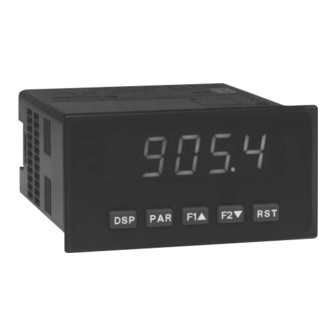
MODEL DP5 – 1/8 DIN ANALOG INPUT PANEL METERS
U
L
C
US LISTED
US LISTED
4
IND. CONT . EQ.
51EB
GENERAL DESCRIPTION
The DP5 Panel Meters offer many features and performance capabilities to
suit a wide range of industrial applications. These meters are available in three
different models to handle various analog inputs, including DC Voltage/Current,
Process, and Temperature Inputs. Refer to pages 4 and 5 for the details on the
specific models.
The meters provide a MAX and MIN reading memory with programmable
capture time. The capture time is used to prevent detection of false max or min
readings which may occur during start-up or unusual process events.
The signal totalizer (integrator) can be used to compute a time-input product.
This can be used to provide a readout of totalized flow, calculate service
intervals of motors or pumps, etc. The totalizer can also accumulate batch
weighing operations.
Once the meters have been initially configured, the parameter list may be
locked out from further modification.
The meters have been specifically designed for harsh industrial environments.
With NEMA 4X/IP65 sealed bezel and extensive testing of noise effects to CE
requirements, the meter provides a tough yet reliable application solution.
DIMENSIONS In inches (mm)
PROCESS, VOLTAGE, CURRENT, AND TEMPERATURE INPUTS
5-DIGIT 0.56" HIGH LED DISPLAY
PROGRAMMABLE FUNCTION KEYS/USER INPUT
9 DIGIT TOTALIZER (INTEGRATOR) WITH BATCHING
OPTIONAL CUSTOM UNITS OVERLAY W/BACKLIGHT
NEMA 4X/IP65 SEALED FRONT BEZEL
SAFETY SUMMARY
All safety related regulations, local codes and instructions that appear in this
literature or on equipment must be observed to ensure personal safety and to
prevent damage to either the instrument or equipment connected to it. If
equipment is used in a manner not specified by the manufacturer, the protection
provided by the equipment may be impaired.
CAUTION: Risk of Danger.
Read complete instructions prior to
installation and operation of the unit.
Note: Recommended minimum clearance (behind the panel) for mounting clip installation is
2.1" (53.4) H x 5.0" (127) W.
1
Bulletin No. DP5-E
Drawing No. LP0546
Released 12/07
CAUTION: Risk of electric shock.
Advertisement
Table of Contents

Subscribe to Our Youtube Channel
Related Manuals for red lion DP5


Summary of Contents for red lion DP5
- Page 1 GENERAL DESCRIPTION SAFETY SUMMARY The DP5 Panel Meters offer many features and performance capabilities to All safety related regulations, local codes and instructions that appear in this suit a wide range of industrial applications. These meters are available in three...
-
Page 2: Table Of Contents
ABLE ONTENTS Ordering Information ....2 Setting the Jumpers ....6 General Meter Specifications. -
Page 3: General Meter Specifications
ENERAL ETER PECIFICATIONS 1. DISPLAY: 5 digit, 0.56" (14.2 mm) red LED, (-19999 to 99999) 14. ENVIRONMENTAL CONDITIONS: 2. POWER: Operating Temperature Range: 0 to 50°C AC Versions: Storage Temperature Range: -40 to 60°C AC Power: 85 to 250 VAC, 50/60 Hz, 10 VA Operating and Storage Humidity: 0 to 85% max. -
Page 4: Universal Dc Input Panel Meter
DP5D - U DC I ODEL NIVERSAL NPUT FOUR VOLTAGE RANGES (300 VDC Max) FIVE CURRENT RANGES (2A DC Max) 24 VDC TRANSMITTER POWER DP5D SPECIFICATIONS INPUT RANGES: INPUT ACCURACY* ACCURACY* IMPEDANCE/ CONTINUOUS RESOLUTION RANGE (18 to 28°C) (0 to 50°C) COMPLIANCE OVERLOAD 0.03% of reading... -
Page 5: Thermocouple And Rtd Input Meter
DP5T - T RTD I ODEL HERMOCOUPLE AND NPUT THERMOCOUPLE AND RTD INPUTS CONFORMS TO ITS-90 STANDARDS TIME-TEMPERATURE INTEGRATOR DP5T SPECIFICATIONS READOUT: Resolution: Variable: 0.1, 0.2, 0.5, or 1, 2, or 5 degree Scale: F or C Offset Range: -19,999 to 99,999 display units RTD INPUTS: THERMOCOUPLE INPUTS: Type: 3 or 4 wire, 2 wire can be compensated for lead wire resistance... -
Page 6: Installing The Meter
The panel The DP5 meets NEMA 4X/IP65 requirements for indoor use when properly latch should be engaged in the farthest forward slot possible. To achieve a installed. -
Page 7: Wiring The Meter
DP5P Jumper Selection Main JUMPER SELECTIONS Circuit indicates factory setting. Board USER INPUT JUMPER LOCATION DP5T Jumper Selection RTD Input Jumper One jumper is used for RTD input ranges. Select the proper range to match the RTD probe being used. It is not necessary to remove this jumper when not using RTD probes. Main Circuit JUMPER SELECTIONS... - Page 8 3.1 POWER WIRING AC Power DC Power Terminal 1: VAC Terminal 1: +VDC Terminal 2: VAC Terminal 2: -VDC 3.2 INPUT SIGNAL WIRING DP5D INPUT SIGNAL WIRING Before connecting signal wires, the Input Range Jumper should be verified for proper position. Voltage Signal Current Signal Current Signal (2 wire...
-
Page 9: Reviewing The Front Buttons And Display
DP5T INPUT SIGNAL WIRING CAUTION: Sensor input common is NOT isolated Thermocouple 3-Wire RTD 2-Wire RTD from user input common. In order to preserve the safety of the meter application, the sensor input common must be suitably isolated from hazardous live earth referenced voltages;... -
Page 10: Programming The Meter
5.0 P ROGRAMMING THE ETER OVERVIEW PROGRAMMING MENU DISPLAY MODE STEP BY STEP PROGRAMMING INSTRUCTIONS: The meter normally operates in the Display Mode. In this mode, the meter displays can be viewed consecutively by pressing the key. The PROGRAMMING MODE ENTRY (PAR KEY) annunciators to the left of the display indicate which display is currently shown;... - Page 11 5.1 MODULE 1 - S IGNAL NPUT ARAMETERS PARAMETER MENU DP5T PARAMETER MENU Refer to the appropriate Input Range for the selected TEMPERATURE SCALE meter. Use only one Input Range, then proceed to Display Decimal Point. °F °C Select the temperature scale. This selection applies for Input, MAX, MIN, DP5D INPUT RANGE and TOT displays.
- Page 12 FILTER SETTING* INPUT VALUE FOR SCALING POINT 2 seconds The input filter setting is a time constant expressed in tenths of a second. The For Key-in ( ), enter the known second Input Value by using the arrow filter settles to 99% of the final display value within approximately 3 time keys.
- Page 13 5.2 MODULE 2 - U NPUT AND RONT ANEL UNCTION ARAMETERS PARAMETER MENU The user input is programmable to perform specific meter control functions. RELATIVE/ABSOLUTE DISPLAY While in the Display Mode or Program Mode, the function is executed the instant the user input transitions to the active state. The front panel function keys are also individually programmable to perform specific meter control functions.
- Page 14 RESET TOTALIZER RESET, SELECT, ENABLE MAXIMUM DISPLAY When activated (momentary action), the Maximum value is set to the present Input Display value. Maximum continues from that value while active (maintained action). When the user input is released, Maximum detection stops and holds its When activated (momentary action), flashes and the Totalizer resets to value.
- Page 15 5.4 MODULE 4 - S ECONDARY UNCTION ARAMETERS PARAMETER MENU MAX CAPTURE DELAY TIME* DISPLAY OFFSET VALUE* sec. This parameter does not apply for the DP5T. When the Input Display is above the present MAX value for the entered delay time, the meter will capture that display value as the new MAX reading. A delay time helps to avoid false captures of sudden short spikes.
- Page 16 5.5 MODULE 5 - T OTALIZER NTEGRATOR ARAMETERS PARAMETER MENU TOTALIZER HIGH ORDER DISPLAY The totalizer accumulates (integrates) the Input Display value using one of When the total exceeds 5 digits, the front panel annunciator TOT flashes. In two modes. The first is using a time base. This can be used to compute a time- this case, the meter continues to totalize up to a 9 digit value.
-
Page 17: Factory Service Operations
5.9 MODULE 9 - F ACTORY ERVICE PERATIONS PARAMETER MENU RESTORE FACTORY DEFAULTS DP5P - Input Calibration Use the arrow keys to display and press PAR. WARNING: Calibration of this meter requires a signal source with an The meter will display and then return to accuracy of 0.01% or better. - Page 18 The Company disclaims all liability for any affirmation, promise or representation with respect to the products. The customer agrees to hold Red Lion Controls harmless from, defend, and indemnify RLC against damages, claims, and expenses arising out of subsequent sales of RLC products or products...
-
Page 19: Parameter Value Chart
PARAMETER VALUE CHART Programmer ________________ Date ________ DP5 Model Number _______ Meter# _____________ Security Code __________ Secondary Function Parameters 4-SEC 1-INP Signal Input Parameters FACTORY FACTORY DISPLAY PARAMETER USER SETTING DISPLAY PARAMETER USER SETTING SETTING SETTING 0. 1 HI-t MAX CAPTURE DELAY TIME... -
Page 20: Programming Overview
DP5 PROGRAMMING QUICK OVERVIEW...
Need help?
Do you have a question about the DP5 and is the answer not in the manual?
Questions and answers