Table of Contents
Advertisement
Quick Links
Advertisement
Table of Contents

Subscribe to Our Youtube Channel
Related Manuals for AIMS Power PWRINV10KW12V


Summary of Contents for AIMS Power PWRINV10KW12V
- Page 1 V 2.0 DC TO AC POWER INVERTER PWRINV10KW12V Instruction Manual...
- Page 2 V 2.0 Introduction The AIMS Power 10,000 watt inverter is the most technology advanced mobile DC to AC power inverter available. AIMS also offers the 8,000 Watt 12V or 12,000 Watt 24V. This inverter is used in a wide range of applications including back up power for remote homes, off-grid systems, RVs, boats, commercial vehicles and mobile businesses.
-
Page 3: Front View
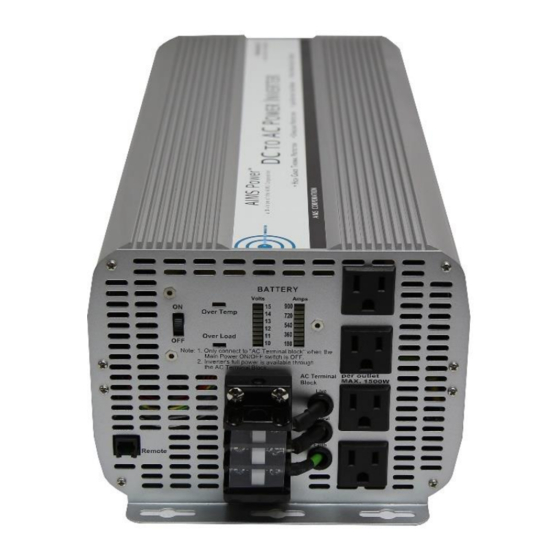
V 2.0 FUNCTIONS FRONT VIEW D: Bar meters B: Over temperature indicator A: On/Off switch C: Over load E: AC outlets indicator G: AC terminal Block F: Remote port A. On/Off switch: Leave in the OFF position during installation. B. Over temperature indicator: Lights when inverter protects itself against overheating. Inverter shuts down while indicator is on. -
Page 4: Rear View
V 2.0 A: Fan REAR VIEW B: Battery terminal (-) B: Battery terminal (+) C: Chassis grounding A: Fan: Do not obstruct, allow at least 12 inches for air flow. B: Battery terminals: Connect to 12V, or 24V, or 36V, or 48V (depending on inverter model) battery (s) or other DC power source. -
Page 5: Installation
V 2.0 3. Set the power switch to the on position. Check the meters and indicators on the front panel of the inverter. The voltage bar graph should indicate 11 to 14 volts depending on the voltage of the power source. If it does not, check your power source and the connections to inverter. The other indicators should be off. -
Page 6: Operation
V 2.0 Red (+) * 2 Black (-) * 2 BLACK Caution! DO NOT allow the wires to cross or touch each other. Install the cables facing away from each other and screw tightly. When connecting the battery cables to the terminals of the inverter, make sure they do not touch the case. - Page 7 V 2.0 1. Controls and indicators The ON/OFF switch turns the control circuit in the power inverter on and off. It does not disconnect power from the power inverter. When the switch is in the OFF position, the power inverter draws no current from battery. When the switch is in the ON position but with no load, the power inverter draws less than 450 mA.
-
Page 8: Troubleshooting
V 2.0 Some induction motors used in refrigerators, freezers, pumps, and other motor operated equipment require very high surge currents to start. The power inverter may not be able to start some of these appliances even though their rated current draw is within the rating of the power inverter. If a motor refuses to start, observe the battery voltage indicator while trying to start the motor. - Page 9 V 2.0 -Keep the cables between the battery and the power inverter as short as possible and twist them together with about 2 to 3 twists per foot. This minimizes radiated interference from the cables. Problem and Symptoms Possible Cause Solution Low output voltage If using a non-RMS meter you could...
-
Page 10: Specifications
V 2.0 SPECIFICATIONS MODEL NO PWRINV10KW12V DC Input Voltage 12V (10-16V) Output Wave Form Modified Sine Wave Output Power 10,000W Surge Power Capacity 20,000W for 40milsecs Efficiency Over 90% No Load Current <1.8A Thermal DC 10.5 + _ 0.5 V Battery Low Alarm DC 9.5 + _ 0.5 V... - Page 11 This warranty is valid worldwide with the exception that freight and duty charges incurred outside the contiguous 48 United States will be prepaid by customer. Except as provided above, AIMS Power makes no warranty of any kind, express or implied, including without limitation the implied warranties of merchantability and fitness for a particular purpose.
- Page 12 V 2.0...
Need help?
Do you have a question about the PWRINV10KW12V and is the answer not in the manual?
Questions and answers