
Related Manuals for AIMS Power PWRINV500012W


Summary of Contents for AIMS Power PWRINV500012W
- Page 1 V 2.0 DC TO AC POWER INVERTER PWRINV500012W PWRINV500024W PWRINV500036W PWRINV500048W Instruction Manual...
-
Page 2: Warning And Safety
V 2.0 INTRODUCTION The AIMS Power 5000 Watt inverters are the most advanced line of mobile DC to AC power systems available. AIMS offers the 5000 Watt inverter in 12V, or 24V, or 36V or 48V DC. This model is used in a wide range of applications including back up power for remote homes, off-grid systems, RVs, boats, commercial vehicles and mobile businesses. - Page 3 V 2.0 Note: Performance of this unit may vary depending on the available battery power or appliance wattage. Warning: The warnings, cautions, and instructions discussed in this instruction manual cannot cover all possible conditions and situations that may occur. It must be understood by the operator that common sense and caution are factors which cannot be built into this product and must be supplied by operator.
-
Page 4: Front View
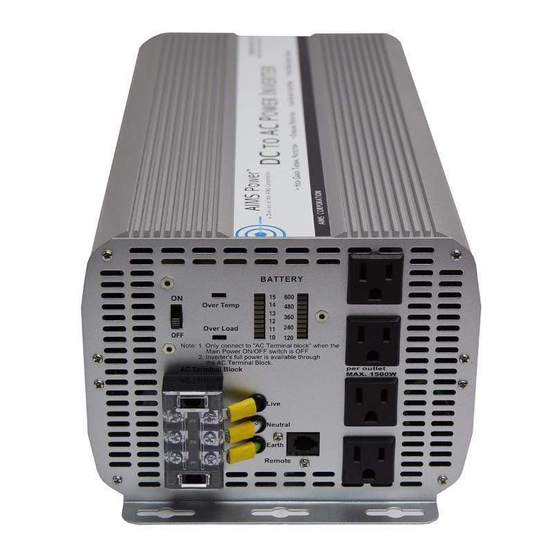
V 2.0 FUNCTIONS FRONT VIEW D: Bar meters B: Over temperature indicator A: On/Off switch C: Over load E: AC outlets indicator G: AC terminal Block F: Remote port A. On/Off switch: Leave in the OFF position during installation. B. Over temperature indicator: Lights when inverter protects itself against overheating. Inverter shuts down while indicator is on. -
Page 5: Rear View
V 2.0 REAR VIEW A: Fan B: Battery terminal (-) B: Battery terminal (+) C: Chassis grounding A: Fan: Do not obstruct, allow at least 12 inches for air flow. B: Battery terminals: Connect to 12V, or 24V, or 36V, or 48V (depending on inverter model) battery (s) or other DC power source. -
Page 6: Installation
V 2.0 The other indicators should be off. 4. Set power inverter switch to the OFF position, the indicator lights may blink and the internal alarm may sound momentarily. This is normal. Plug the test load into the AC receptacle on the front panel of the inverter. Leave the test load switch off. 5. -
Page 7: Operation
V 2.0 Red (+) Black (-) BLACK Caution! DO NOT allow the wires to cross or touch each other. Install the cables facing away from each other and screw tightly. When connecting the battery cables to the terminals of the inverter, make sure they do not touch the case. - Page 8 V 2.0 1. Controls and indicators The ON/OFF switch turns the control circuit in the power inverter on and off. It does not disconnect power from the power inverter. When the switch is in the OFF position, the power inverter draws no current from battery. When the switch is in the ON position but with no load, the power inverter draws less than 450 mA.
-
Page 9: Troubleshooting
V 2.0 Some induction motors used in refrigerators, freezers, pumps, and other motor operated equipment require very high surge currents to start. The power inverter may not be able to start some of these appliances even though their rated current draw is within the rating of the power inverter. If a motor refuses to start, observe the battery voltage indicator while trying to start the motor. - Page 10 V 2.0 -Make sure that the antenna feeding your television provides an adequate ("snow free") signal and that you are using good quality cable between the antenna and the television. -Move the television as far away from the power inverter as possible. -Keep the cables between the battery and the power inverter as short as possible and twist them together with about 2 to 3 twists per foot.
-
Page 11: Specifications
V 2.0 SPECIFICATIONS MODEL PWRINV500012W PWRINV500024W PWRINV500036W PWRINV500048W DC Input Voltage Output Wave Form Modified Sine Wave Operating Voltage 10V-16V 20V-32V 30V-45V 40V-60V Output Power 5000W 10,000W for 40 mil secs Surge Power Capacity Efficiency >90% No Load Current Switch on <1 A DC. Switch off <.2mA DC Thermal 10.5V +/- .5V-... - Page 12 In no event shall AIMS be liable for indirect, special or consequential damages. This warranty only applies to AIMS Power branded products. All other name brand products are warranted by and according to their respective manufacturer.
Need help?
Do you have a question about the PWRINV500012W and is the answer not in the manual?
Questions and answers