Table of Contents
Advertisement
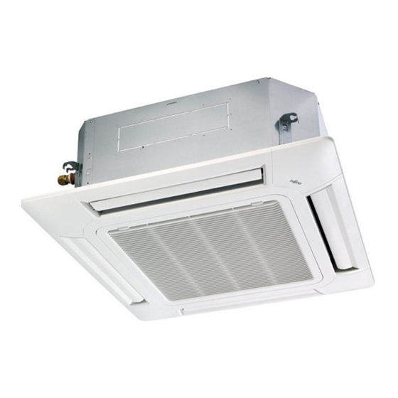
SPLIT TYPE
AIR CONDITIONER
CASSETTE TYPE (50Hz)
Indoor unit
AUHG36LRLA
AUHG45LRLA
AUHG54LRLA
CONTENTS
SPECIFICATIONS . . . . . . . . . . . . . . . . . . .
DIMENSIONS. . . . . . . . . . . . . . . . . . . . . . .
REFRIGERANT SYSTEM DIAGRAM . . . .
CIRCUIT DIAGRAM . . . . . . . . . . . . . . . . . .
INDOOR PCB CIRCUIT DIAGRAM . . . . . .
ERROR DETECTION. . . . . . . . . . . . . . . .
PARTS (DECORATION PANEL) . . . . . . .
PARTS (INDOOR UNIT) . . . . . . . . . . . . .
PARTS (OUTDOOR UNIT) . . . . . . . . . . .
ACCESSORIES . . . . . . . . . . . . . . . . . . . .
Outdoor unit
AOHG36LATT
AOHG45LATT
AOHG54LATT
1
2
4
5
6
10
. . .
17
21
24
28
31
Advertisement
Table of Contents

Related Manuals for General AUHG36LRLA


Summary of Contents for General AUHG36LRLA
-
Page 1: Table Of Contents
SPLIT TYPE AIR CONDITIONER CASSETTE TYPE (50Hz) Indoor unit Outdoor unit AUHG36LRLA AOHG36LATT AUHG45LRLA AOHG45LATT AUHG54LRLA AOHG54LATT CONTENTS SPECIFICATIONS ....DIMENSIONS..... . . -
Page 2: Specifications
SPECIFICATIONS ELECTRICAL DATA NOISE LEVEL Cooling & Heating High TYPE 44 dB 46 dB 47 dB INDOOR UNIT AUHG36LRLA AUHG45LRLA AUHG54LRLA Medium 39 dB 42 dB 43 dB INDOOR UNIT OUTDOOR UNIT AOHG36LATT AOHG45LATT AOHG54LATT 36 dB 40 dB 41 dB COOLING CAPACITY 10.0 kW... -
Page 3: Dimensions
DIMENSIONS Drain pipe INDOOR UNIT DECORATION PANEL (Unit : mm) Gas pipe Liquid pipe Side view Bottom view 795 (Hanging bolt position) Top view 2012.04.26... - Page 4 OUTDOOR UNIT (unit : mm) air flow 2008.11.13...
-
Page 5: Refrigerant System Diagram
REFRIGERANT SYSTEM DIAGRAM OUTDOOR UNIT INDOOR UNIT Refrigerant flow Refrigerant Pipe Cool Pressure 15.88mm (5/8") Check Valve Heat Strainer 3-Way Valve 4-way Valve Pressure Sensor Heat Heat Exchanger Exchanger Muffler Accumulator Compressor Refrigerant Pipe Expansion 9.52mm (3/8") Valve Strainer Strainer Thermistor (Compressor) 3-Way Valve Thermistor (Room) -
Page 6: Circuit Diagram
CIRCUIT DIAGRAM OUTDOOR UNIT INDOOR UNIT OPTION ( CONNECTOR ) BLACK THERMISTOR REFER TO THE BLACK ( PIPE TEMP. ) TECHNICAL MANUAL THERMISTOR ( ROOM TEMP. ) ORANGE YELLOW STEPPING MOTOR CN12 PINK 1 2 3 BLUE 1 2 3 1 2 3 1 2 3 1 2 3... -
Page 7: Indoor Pcb Circuit Diagram
INDOOR PCB CIRCUIT DIAGRAM CONTROL UNIT THERMISTOR AUHG36LRLA : EZ-0122PHSE B02B-XASK-1-A ( ROOM TEMP. ) WHITE AUHG45LRLA : EZ-0122RHSE B02B-XAYK-1-A YELLOW AUHG54LRLA : EZ-0122SHSE THERMISTOR BLACK B02B-XAKK-1-A BLACK ( PIPE TEMP. ) BLACK B5P-SHF-1AA WHITE TERMINAL INDICATOR PCB 2 (N) - Page 8 INDOOR UNIT MAIN PCB AUHG36LRLA : K06AK-121AHSE-C1 AUHG45LRLA : K06AK-121BHSE-C1 AUHG54LRLA : K06AK-121CHSE-C1 R1 - R3 B02B-XASK-1-A 1SS355 10k <1/10W> x 3 THERMISTOR ( ROOM TEMP. ) I C8 FLOAT SWITCH 13.5V NJM7812 B03B-PASK-1 <1/10W> 1.0k B02B-XAYK-1-A B03B-XARK-1-A <F> <1/10W>...
- Page 9 R103 340V D108 13.5V D2FL20U <RS-2W> T101 C108 ZFT22B03-C 4700 <FNS> C113 R111 I C26-14 1000/ R104 <1/10W> 330k D102 <2W> F101 1SR139-600 C114 3.15A 250V 0.01 <KH> C109 D107 220p L101 Q101 D106 C115 RD16 FC51FL x 2 <BN> LF101 <REP-28>...
- Page 10 INDOOR UNIT INDICATOR PCB ( OPTION ) K06AG-1000HSE-D0 R201 220 <1/4W> D201 SLR-325MC GREEN CN201 S07B-PASK-2 R202 390 <1/4W> D202 SLR-325DC ORANGE R203 220 <1/4W> D203 SLR-325MC GREEN TO MAIN PCB C202 C201 <F> SW201 EVQPAG04K PHA201 P I C-37143TH5 2012.03.07...
-
Page 11: Outdoor Pcb Circuit Diagram
OUTDOOR PCB CIRCUIT DIAGRAM INVERTER ASSEMBLY AOHG36LATT : EZ-01222HUE REACTOR L1 - L3 AOHG45LATT : EZ-0111WHUE THERMISTOR ( HEATSINK TEMP. ) 17mH 14A x 3 AOHG54LATT : EZ-0111YHUE UL1007 UL1007 AWG24 AWG24 WHITE BLACK UL1015 UL1015 UL1015 UL1015 UL1015 UL1015 AWG14 AWG14 AWG14... - Page 12 OUTDOOR UNIT MAIN PCB REACTOR AOHG36LATT : K07AK-1200HUE-C1 CN102 2-1747052-3 R101 P I N 101 P I N 102 AOHG45LATT : K07AK-1101HUE-C1 BLUE ZPR0RCH400 D101 340V PFC5000-0702F x 2 CN101 LL25XB60 L101 AOHG54LATT : K07AK-1102HUE-C1 B3P5-VH-B RCV1904-050PF07 WHITE L151 D151 C104 AC I N BL02Rn1...
- Page 13 OUTDOOR UNIT TRANSISTOR PCB K11CA-1200HUE-TR1 TM802 YELLOW P I N D908 US1J TM803 BLUE R900 R901 R902 N I N P I N801 <2.8W> <7W> <7W> L960 RGDU7M RGGS7 RGGS7 BL02Rn1 R940 - R949 DC + P I N800 0.1 <1W> 1% x 10 L900 BL02Rn1 K880...
- Page 14 OUTDOOR UNIT ACTIVE FILTER PCB - 1 K-11BZ-1100HUE-AF0 REACTOR L1 - L3 12A 18mH From Filter PCB TM504 TM300 TM500 DC+ OUT L1 I N W300 TM301 TM501 L2 I N W301 TM302 TM502 L3 I N W302 TM505 N OUT CT301, CT300 D351 FC-1-X x 2...
- Page 15 OUTDOOR UNIT ACTIVE FILTER PCB - 2 K11BZ-1100HUE-AF0 Jump To Page1 Jump To Page1 R530, R536 47k 1% x 2 D530 I C510-3 D470 R590 R539 C530 RB751V BA2901F DAN217U D533 R533 RB751V <F> R470 - R474 R503 8.2k 1% C591 220k <1/3W>...
- Page 16 OUTDOOR UNIT FILTER PCB K07AQ-0700HUE-FL0 3 Phase 380 - 415V 50Hz VA202 L200 L201 H-0017-2 x 2 820V RC3V3812-009PF05 RC3V3812-009PF05 FH200 FH201 L1 I N <TNR> 12A 0.9mH 12A 0.9mH TM203 L1 OUT TM200 VA200 P200 <NSHV4> 820V <TNR> H-0017-2 x 2 L2 I N FH202 FH203...
- Page 17 OUTDOOR UNIT CAPACITOR PCB K07AP-0700HUE-P0 W700 W702 P I N P OUT YELLOW ORANGE R700 R702 C700 C702 660/ 660/ 450V <RS-5W> <RS-5W> 450V R701 R703 C701 C703 660/ 660/ <RS-5W> <RS-5W> 450V 450V W701 W703 N OUT N I N BLUE PURPLE 2012.02.29...
-
Page 18: Error Detection
ER R OR D ETEC TION Indoor unit Indoor unit Wired Wired OPERATION TIMER ECONOMY remote Description OPERATION TIMER ECONOMY remote Description INDOOR UNIT lamp lamp lamp lamp lamp lamp control control (green) (orange) (green) (green) (orange) (green) and WIRED REMOTE CONTROL Discharge temp. - Page 19 OUTDOOR UNIT TEST RUN CAUTION Always turn on the power 6 hours prior to the start of the operation in order to protect the compressor. 1. Check items before performing the test run 2.1. Operating procedures for the test run Make sure to perform the test run.
- Page 20 OUTDOOR UNIT ERROR CODE DISPLAY Display when an error occurs TEST PUMP POWER LOW NOISE PEAK CUT DOWN ERROR MODE (L1) (L2) (L3) (L4) (L5) (L6) (L7) Blinks (Hi-speed) Check that the ERROR LED blinks, and then short-press the [ENTER] switch once. Display mode : ON The number of blinks of the LED indicates the type of error.
- Page 21 2. Pump down procedure OUTDOOR UNIT PUMP DOWN (Refrigerant collecting operation) (1) Check the 3-way valves (both at the liquid side and gas side) are opened. (2) Turn the power on. Perform the following procedures to collect the refrigerant when moving the indoor unit or outdoor unit TEST PUMP POWER...
-
Page 22: Parts (Decoration Panel)
PARTS DECORATION PANEL UTG-UGGA-W Ref. Description Part number Intake Grille Assy 9378565012 Intake Grille 9378249011 Long Life Filter 9378252011 Filter Guide 9378253018 Hook Bracket 9378435018 Grille Hook 9378250017 2012.04.26... - Page 23 DECORATION PANEL UTG-UGGA-W Ref. Description Part number Decoration Panel 9378242012 Corner Panel A 9378243019 Corner Panel (GENERAL) 9378243033 Panel Cover A 9378261013 Panel Cover B 9378262010 Drain Cover 9378359017 2012.03.16...
- Page 24 DECORATION PANEL UTG-UGGA-W Ref. Description Part number Flap 9378254015 Poli Slider 9375541019 Joint C 9378357013 Step motor 9900467005 Gear A 9378256019 Motor Holder 9378255012 Joint A 9378258013 Joint B 9378259010 Gear B 9378257016 Joint Shaft 9378260016 Flap Spring 9378356016 2012.03.16...
-
Page 25: Parts (Indoor Unit)
PARTS INDOOR UNIT Ref. Description Part number Ref. Description Part number Top Plate Assy 9378395015 Motor, DC Brushless 9602716005 Cabinet A Sub Assy 9378594012 Motor Rubber 9378223011 Cabinet B Sub Assy 9378595019 Turbo Fan Assy 9378228016 Cabinet C Sub Assy 9378570016 Turbo Fan Washer 9378394018... - Page 26 INDOOR UNIT Ref. Description Part number Evaporator Total Assy 9378580053 Coupling Pipe Assy 9373038627 Wind Guide Board 9378236011 2012.03.16...
- Page 27 INDOOR UNIT Ref. Description Part number Sensor Holder 9378329010 Float Switch 9900465018 Pump Assy 9900464011 Drain Pump Holder B 9375518011 Pump Rubber 9378426016 Drain Hose 9378212015 Drain Port 9378213012 Drain Pan Assy 9378207011 Bell Mouth 9378227019 Terminal Wire Cover 9378548015 Drain Cap 9375502010 Drain Hose...
- Page 28 INDOOR UNIT Ref. Description Part number PCB Holder 9378205017 Power Supply PCB 9707398366 Main PCB (36) 9709245460 Main PCB (45) 9709245477 Main PCB (54) 9709245484 Terminal 3P 9306489045 Terminal 3P 9703345012 Thermistor Holder A 9378206014 Thermistor Holder B 9378330016 Room Thermistor 9900445010 Pipe Thermistor 9900470012...
-
Page 29: Parts (Outdoor Unit)
PARTS OUTDOOR UNIT Ref. Description Parts number Ref. Description Parts number Top Panel Sub Assy 9374417032 Reactor Assy 9900641016 Front Panel Sub Assy 9374414130 Motor, DC Brushless 9602843046 Sevice Panel Sub Assy 9374415076 Propeller Fan Assy 9366378020 Emblem Rear 9372171059 Condenser A Sub Assy 9374420261 Pipe Cover Front... - Page 30 OUTDOOR UNIT 4-way Valve Assy Ref. Description Parts number Expansion Valve Coil 9900190057 Expansion Valve Assy 9370947182 Strainer Assy 9372524039 Solenoid 9970113024 4-way Valve Assy 9374425273 3-way Valve Assy 9379079006 3-way Valve Assy 9379077002 Sensor 9900505011 Accumulator Assy 9375250096 Compressor Sub Assy 9374423286 Expansion Valve Assy 2012.03.16...
- Page 31 OUTDOOR UNIT (yellow) (white) (red) (white) (connector : blue) Ref. Description Parts number Main PCB (36) 9707627091 Main PCB (45) 9707627077 Main PCB (54) 9707627084 Filter PCB 9707609011 Active Filter PCB 9709008010 Capacitor PCB 9707608014 Transistor PCB 9709010020 (red) Reactor Assy 9900481018 Terminal 9900428082...
-
Page 32: Accessories
ACCESSORIES INDOOR UNIT DECORATION PANEL Name and Shape Q'ty Part number Part number Name and Shape Q'ty Template For mounting decoration Hexigon (Carton top) For installing indoor unit 9378552029 0700087103 Screw panel Washer Screw For installing grille For installing indoor unit 0700132278 0700009037 holding wire... - Page 33 OPTIONAL PARTS Parts name Model name For air conditioner operation IR receiver unit UTY-LRH*A2 For air conditioner operation Wired Remote Control UTY-RNN*M Install the plate at outlet Air outlet shutter plate UTR-YDZC when carrying out 3-way direction operation Insulation kit for High UTZ-KXGA humidity External connect kit...
- Page 34 1204G4044...
Need help?
Do you have a question about the AUHG36LRLA and is the answer not in the manual?
Questions and answers