Table of Contents
Advertisement
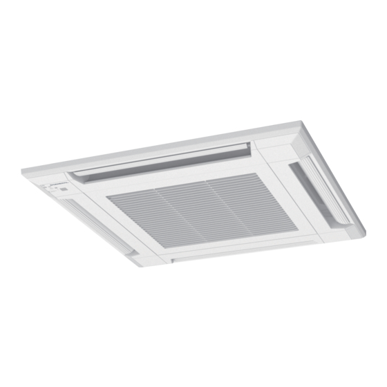
AIR CONDITIONER
3-unit multi-split type
DESIGN & TECHNICAL MANUAL
INDOOR
AUXG07KVLA
AUXG09KVLA
AUXG12KVLA
AUXG14KVLA
AUXG18KVLA
ASHG07KMCC
ASHG09KMCC
ASHG12KMCC
ASHG14KMCC
OUTDOOR
AOHG18KBTA3
AOHG24KBTA3
ARXG07KSLAP
ARXG07KLLAP
ARXG09KSLAP
ARXG09KLLAP
ARXG12KSLAP
ARXG12KLLAP
ARXG14KSLAP
ARXG14KLLAP
ARXG18KSLAP
ARXG18KLLAP
ASHG07KETA
ASHG07KETA-B
ASHG09KETA
ASHG09KETA-B
ASHG12KETA
ASHG12KETA-B
ASHG14KETA
ASHG14KETA-B
ASHG07KGTB
ASHG18KMTB
ASHG09KGTB
ASHG12KGTB
ASHG14KGTB
ABHG18KRTA
AGHG09KVCA
AGHG12KVCA
AGHG14KVCA
DR_MU024EG_01
2020.11.12
Advertisement
Table of Contents


Need help?
Do you have a question about the AUXG07KVLA and is the answer not in the manual?
Questions and answers